College of Veterinary Medicine Auburn University Auburn, Alabama 36849-3501 USA
Plastination is a process for tissue preservation in which tissue fluid (and some lipid) is replaced with a curable polymer such as silicone rubber, epoxy or polyester. This process is undergoing rapid continual development. At present, few equipment items or systems, intended expressly for plastination, are available from commercial sources. For example, most vacuum systems in use today are home-designed and homemade.
The purpose of, this article is to describe the versatile, two-pump vacuum system presently used in our plastination laboratory. Included in this paper are goals of the project, principles of design, construction comments, cost analysis and evaluation after use.
Vacuum; Plastination; Vacuum control
Paul F. Rumph College of Veterinary Medicine Auburn University Auburn, Alabama 36849-3501 USA

![]()


Plastination is a process for tissue preservation in which tissue fluid (and some lipid) is replaced with a curable polymer such as silicone rubber, epoxy or polyester. This process is undergoing rapid continual development. At present, few equipment items or systems, intended expressly for plastination, are available from commercial sources. For example, most vacuum systems in use today are home-designed and homemade.
The purpose of, this article is to describe the versatile, two-pump vacuum system presently used in our plastination laboratory. Included in this paper are goals of the project, principles of design, construction comments, cost analysis and evaluation after use.
GOALS AND DESIGN
At the outset, several goals were identified. Our plan called for: 1) relative simplicity, 2) minimal cost, 3) commonly available components and, 4) the need for only a moderate level of assembly skills. Because of the almost- universal problem of limited space, size was to be kept to a minimum. Our design was intended to incorporate the following features:
1) for versatility and reliability, vacuum would be generated by two pumps.
2) the system would permit operation of two plastination kettles, individually or concurrently
3) crossover communication between pumps and inlets would allow independent operation of either system with either pump
4) a single battery of manometers would be able to serve either system, as needed
5) traps would be employed to protect the pumps from overflow
6) the entire system would be portable, situated near eyelevel and convenient to use. A schematic diagram of the various configurations is shown in Fig 1
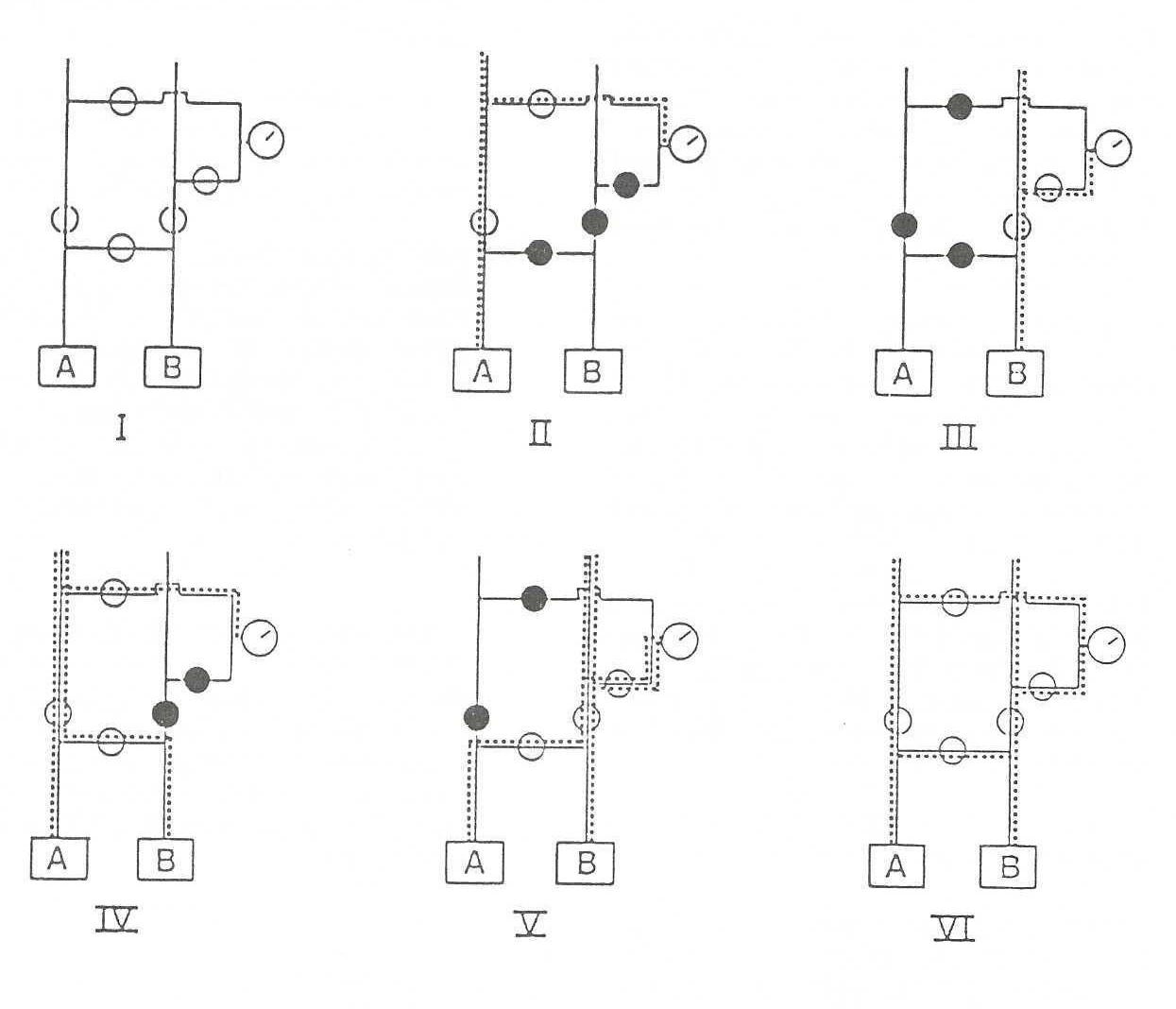 Figure 1. Diagrams of the different configurations of the vacuum apparatus. The squares represent the vacuum pumps; the open circles, the pen valves; and the black circles, the closed valves. A vacuum gauge is represented by a circle at the right of each diagram. The different configurations are: I, basic diagram; II, pump A activating line A; III, pump B activating line B; IV, pumps A and B activating line A; V, pumps A and B activating line B; VI, pumps A and B activating lines A and B. |
ASSEMBLY
After laying out the vacuum circuits and and determining the minimum area into which they would fit, we selected a wooden table from university salvage on which to assemble them. Wooden supports were attached to the table surface, creating compartments for pumps, controls and manometers. Segments of tubing were then cut to lengths sufficient to communicate between these compartments.
Tools required for assembly included a tubing cutter, propane torch, solid wire solder (50/50 tin-lead), flux, ruler and pliers. Teflon tape was used to seal all threaded joints. Construction, including table modification, required about six man-hours.
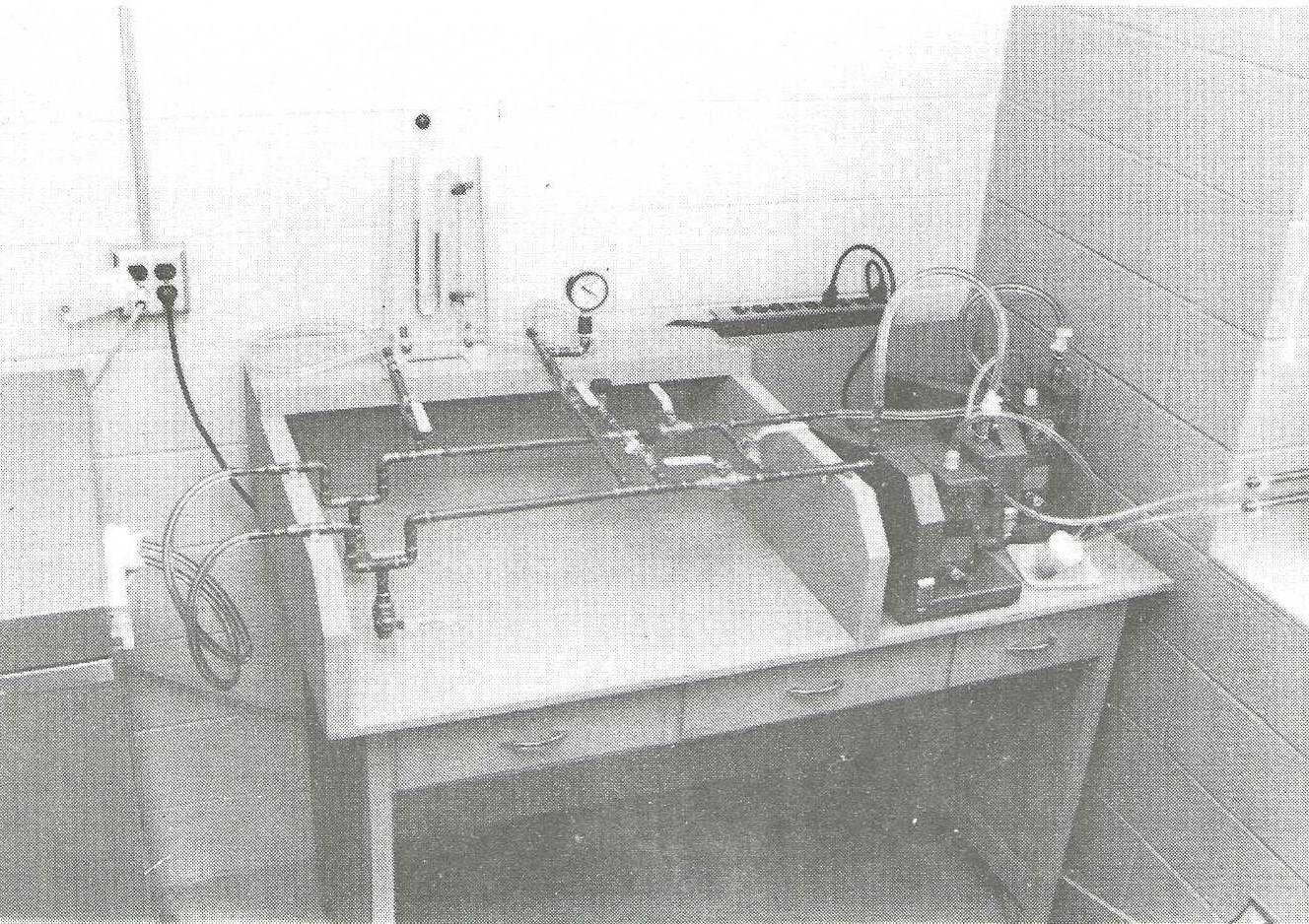
Figure 2. A photograph of the vacuum apparatus. The exhaust lines to the right are connected to copper pipes which pass through the window frame to the outside. A small cup has been rigged to trap oil vapors passing out the exhaust line in use.
The sediment trap and drains were assembled first, followed by the straight portion of the individual lines. Finally, the lines were connected to each other. Lines to the manometers were attached and reducers were installed for the flexible inlet tubing leading to these instruments.
Alignment during soldering was maintained by temporary braces. After soldering, the system was tested by plugging the inlets, closing all inlet valves, pumping down to 10 mm Hg and closing the pump valves. No change of vacuum was noted on either manometer after six hours.
The final configuration of the system is shown in Figure 2. Its components are listed in Table 1. Our cost for each item is included. Fittings and valves were available from local plumbing supply stores.
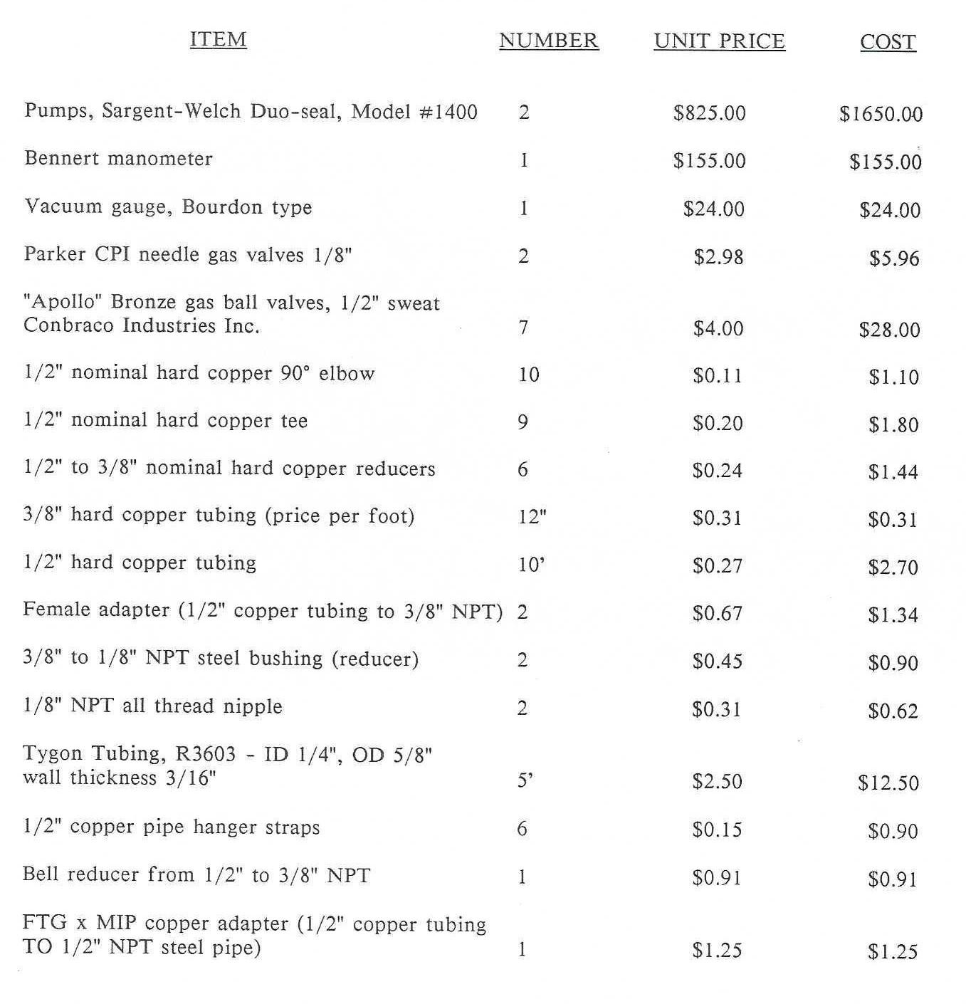 Table 1 |
EVALUATION
Having used the system for forced impregnation, we offer this evaluation: Its performance has been satisfactory in all respects. Pump-down proceeds - smoothly and vacuum is maintained at less than 1 mm Hg. We find the height and arrangement of valves and manometers convenient. No liquid has Collected in the lines. The sediment traps permit opening the system at any during the pump-down sequence without disturbing the vacuum adjustment Calves. This affords quick return to an | established pressure.
We had intended that each pump be able
to work either or both lines. In practice, however, we found that we could not achieve a pressure below 3 mm Hg with one pump working against the other. Placement of shutoff valves at positions A and B in Figure 3 would permit this and would prevent pump oil backflow.
Had sufficient floor space not been available, the entire unit could have been built as a wall unit by mounting the lines on a vertical backboard.
The flexible tubing, manometers and pumps would be common to any system. Thus, the cost analysis presented in this paper applies to our project and is intended to serve only as an example. Since the table was obtained from university surplus and the lumber was scrap, they represented no cost. Total cost of tubing, valves and other fittings was $47.23.
We have described a versatile vacuum system for use in plastination. It was constructed at minimal cost, using commonly available components. We are entirely satisfied with its performance in routine use.
none