Department of Anatomy and Cell Biology and Department of Pathology Queen's University, Kingston, Ontario K7L 3N6 Canada.
In the past many plastinators have shown little interest in setting up a facility for sheet plastination because of the initial costs involved. Unless there is a great demand for sectional anatomy specimens, it is not economically feasible to buy the equipment required for the process. Therefore it is important to develop methods to reduce the costs of this technique. Described here are several ideas and practical solutions to help the plastinator achieve this goal.
Plastination; Sheet Plastination; P35; E12
Wayne Lyons Department of Anatomy and Cell Biology and Department of Pathology Queen's University, Kingston, Ontario K7L 3N6 Canada.

![]()


Due to ever increasing costs, it has become more important to build your own equipment or to re-use old equipment. It is with this thought in mind that we have put together a series of hints and suggestions to simplify the procedures of sheet plastination. The methods of equipment construction and time saving procedures described herein allow the plastinator to produce top quality sections at a much reduced cost.
The following materials and supplies were used to build pieces of equipment used in the sheet plastination technique:
METHODS
The following outlines the construction of several pieces of equipment necessary for handling sections for both the P- 35 and E-12 sheet plastination techniques. All tissue processing techniques followed general procedures as outlined in "Heidelberg Plastination Folder 1985" (von Hagens, 1985).
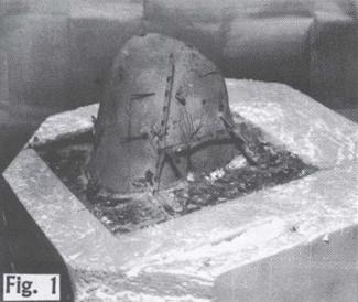
Fig. 1: Recycled styrofoam box with human knee specimen
a. Styrofoam Embedding Boxes (Fig. 1):
To stabilize specimens during cutting, a Styrofoam box was used as a mold into which the fixed specimen was placed. 20% gelatin was then added to the mold and allowed to set. When slicing brain tissue, using a Hobart meat slicer (Hobart, Model 1100) it was advantageous to wet the blade, using moistened paper towelling, during slicing. This facilitated cutting of both the gelatin and the tissue. Small body sections ( e.g. knee joint, etc.) were also easily cut on a band saw when embedded in gelatin prior to cutting. The gelatin helped in orienting the specimens for cutting and small portions of tissue remained intact throughout the procedure (Barnett, 1980).
b. Cooling Fence (Fig. 2):
A cooling fence, used to maintain the frozen state of the tissue during cutting, was constructed of 5.0 mm aluminum sheet metal and measured 6.5cm x 38.0cm x 30.0cm. The fence was equipped with a vented lid and stopcock emptying port. The
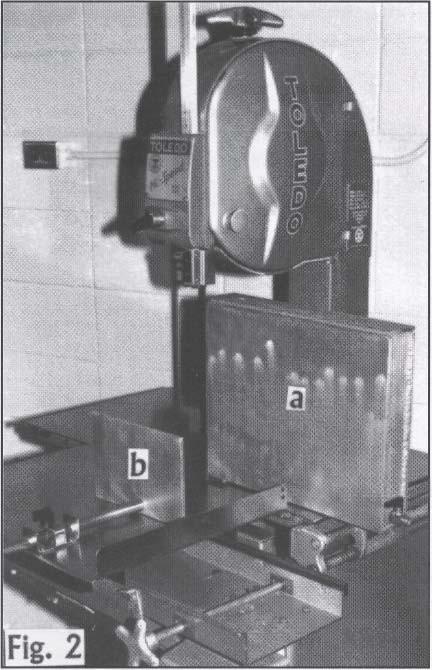
Fig. 2: Modified band saw with cooling fence (a) and feeding mechanism (b) attached.
fence was attached to the thickness guide of the band saw and filled with liquid nitrogen prior to cutting (Weber, 1993).
c ) Feeding Mechanism ( Fig. 2 ):
A Feeding mechanism, used to control the pressure applied to the tissue during slicing, was manufactured of 5mm aluminum sheet metal and measured 14.5cm x 21.5cm. It had a 18mm diameter, 40cm adjustment arm which could be secured by a clamping mechanism attached to it. The clamping mechanism was attached to the moveable feed bed of the band saw.
d. Stainless Steel Plastination Chamber (Fig. 3):
A 20 gauge stainless steel plastination chamber 19.0 cm x 21.0 cm x 30.0 cm (with lid) was purchased from a local heating supply firm. This was used to process the specimens.
e. Plastination Chamber Insert (Fig. 3):
An insert 18.0cm x 20.0cm x 29.0cm. was made for the plastination chamber and used for holding processing racks during the dehydration and infiltration of the tissues. It was constructed from 2.0mm perforated
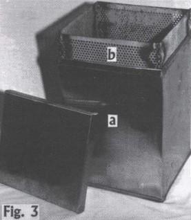
Fig. 3: Stainless steel plastination chamber (a) with insert (b).
steel plates, scavenged from discarded ventilation grids. The plates were cleaned of dirt and old paint using Acetone and then measured, cut to size and all joints were welded.
f. Hardware Cloth Racks (Fig. 4a, 4b):
Racks for transferring sections during processing were constructed from 5.0mm grid hardware cloth (galvanized steel mesh). For our purposes the racks had overall dimensions of 17.0cm x 19.0mm with 5.0mm folded edges, bent in a triangular shape, to facilitate stacking of the sections. These racks, containing the sections, could be placed in the plastination chamber insert for easy movement between processing solutions.
g. Rack Handles (Fig. 4a):
30.0 cm pieces of coat hanger wire were used to construct handles for lifting the hardware cloth racks during processing. The wire was bent in an upside down "U" shape, with the terminal 5.0mm of the U-arms bent to 90°.
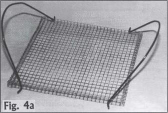 Fig. 4a: Hardware cloth rack with coat hanger wire handle. |
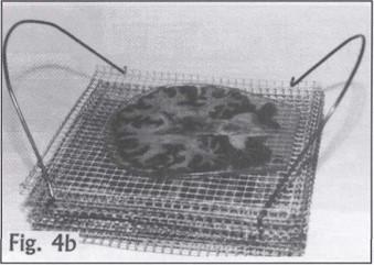 Fig. 4b: Hardware cloth racks stacked for processing of specimens. 'Note- folded edges of racks serve as spacers |
h. Infiltration Chamber (Fig. 5):
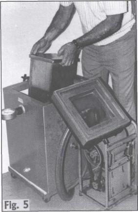
Fig. 5: Large vacuum oven placed on end being used as infiltration chamber. Size required is dependent upon size of plastination chamber used.
A vacuum oven, large enough to accommodate the plastination chamber, was used to infiltrate the specimens. The oven was placed on its end and a monometer was attached in line between the intake of the oven and the vacuum pump. The exhaust of the pump was vented to a fume hood.
i. Curing Rack (Fig. 6a, 6b):
To facilitate the curing of several specimens at a time, a curing rack was constructed from tubular steel and push- fit corner inserts. The following pieces of tubular steel were cut:
4 - 0cm x 2.5cm x 2.5cm
4 - 15.0cm x 2.5cm x 5cm
4 - 0cm x 2.5cm x 2.5cm
68 -10.5cm x 1.0cm x 1.0cm
The 10.5cm pieces where welded along the length of the 84.0cm pieces, at an angle of 105°, at 5.0cm intervals. The rack was assembled using push-fit corner inserts.
j. Filling Funnel (Fig. 7a, 7b):
A 10.0mm diameter funnel for filling the tissue molds during the casting procedure was constructed from 6.0mm clear plastic. Its edge was reinforced with coat hanger wire. The funnel was supported with a circular laboratory retort stand. A flatjaw pincock 16.0mm tubing clamp was used to control the flow of resin from the funnel into the tissue molds.
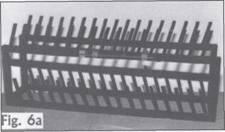 Fig. 6a: Curing rack. May be used single layered or double layered as shown. |
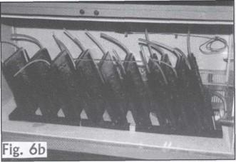 Fig. 6b: Curing rack, single layered, with casted specimens in place. *Note- Uprights of curing rack are welded at an |
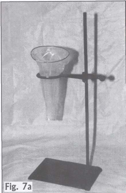 Fig. 7a:Filling funnel constructed of 6.0mm clear plastic. |
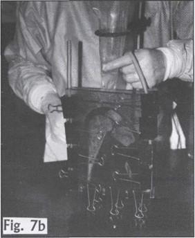 Fig. 7b: Filling funnel being used to fill specimen cast during embedding. |
k. Air Bubble Remover (Fig. 8):
Bubbles were removed from the tissue molds, using a BD Spinal Needle, Type *5l48, 12.7cm long, attached to a BD 10.0 cc syringe. The needle was rinsed with Acetone between uses or when clogged.
l. Gaskets (Fig. 9):
Gaskets used in the construction of casting molds can be made of several different materials. Either solid silicone gaskets or construct gaskets using a combination of a solid gasket and polyethylene tubing may be used. This type of gasket is easily assembled by feeding or blowing (using an air-hose) a smaller diameter (i.e. 6mm OD) solid silicone gasket into a larger diameter (i.e. 6.4mm ID, 9.5mm OD) polyethylene tubing.
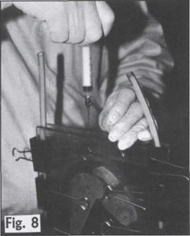 Fig. 8: BD Spinal needle being used to extract bubbles from cast specimen prior to curing. |
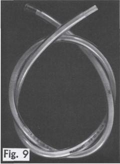 Fig. 9: 6mm OD silicon gasket placed inside of 9.5mm OD polyethylene tubing. |
m. Gasket Holder (Fig. 10):
A gasket holder with a 28.0cm x 22.0cm x 12.0mm plywood base and 8.0cm diameter roller, 28.0cm in length, was constructed using 3.0mm Plexiglass G.
n. Curing Oven (Fig. 11):
An under counter cupboard, heat insulated and fitted with a thermostatically controlled strip heater, was used as a curing chamber. The curing process was done as described by von Hagens.
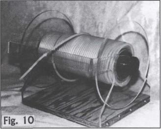 Fig. 10: Gasket holder with silicone gasket. |
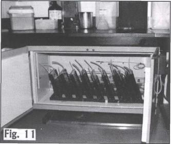 Fig. 11: Undercounter curing oven with specimens in place on curing rack. |
o. Plexiglass Mounts and Legend Holders (Fig. 12):
Several specimen mounts were constructed from 5cm Plexiglass G. The mounts varied in size depending on the type of specimens to be displayed. Legend holders, large enough to accommodate a 7.6cm x 12.7cm file card were fabricated on a bending jig using 3.0mm Plexiglass G (Lyons, 1987).
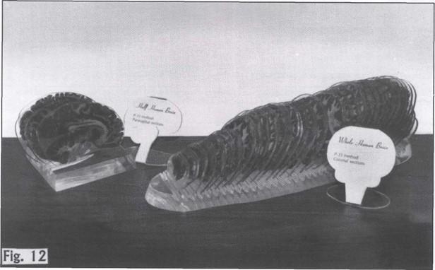 Fig. 12: Plexiglass mounts and legend holders used to display specimens. |
Using gelatin molds to stabilize specimens during slicing (Barnett, 1980), resulted in considerably less damage to them. The gelatin caused no apparent problem during any of the remaining steps of the procedure.
As described by Weber (1993), slicing of anatomical material with a band saw, is much easier when carried out using a cooling fence. It is also essential in maintaining the integrity of the sections. The cost of this device can vary from a few dollars to several hundred. Therefore, it is important to take care when selecting a manufacturer for your cooling apparatus. We have found that developing a good liaison with your physical plant facilities, engineering departments, etc. can be a money-saving proposition. Use of a feeding mechanism attached to the moveable table of a band saw during the cutting procedure was helpful in equalizing the pressure on the specimens as they were guided through the saw blade. The feeding mechanism maintained a constant pressure on the specimen and helped to minimize the distortion of the sections.
The use of stainless steel processing chambers was governed by the cost involved. We found that it was more cost effective to have containers made locally rather than purchase them from a scientific supplier. It is advisable to include an insert for your vessel(s). By using the insert system of handling, damage to the specimens is minimized.
Using hardware cloth racks for support of the sections during handling also prevented damage. The racks, because of their gridded structure, provided freedom for exchange of processing fluids to all areas of the tissues. They also assured that tissues were separated adequately during the dehydration, defatting and infiltration processes.
Using an existing vacuum oven as an infiltration chamber resulted in considerable savings. It is advantageous if the vacuum oven has a glass insert in the door which allows for careful monitoring of polymer bubbles during the infiltration process. Another advantage of using the vacuum oven was that it provided a chamber for bubble removal in the specimens prior to curing.
Constructing your own curing rack enables you to customize it to your own needs. The push-fit corners allow for easy dismantling. Varying lengths of holders can then be inserted and the unit can be reassembled. This type of construction allows single or double tier curing capacity and provides ideal support for the specimens during curing.
Ease of bubble removal in the specimens, prior to curing, was facilitated by using the BD Spinal Needle. The needle was placed near the bubble to be removed. The inner stylet of the needle was removed and a 10 cc syringe was attached to the needle. The syringe was then retracted and the bubble was drawn into the needle. The advantage of using this technique was that the bubbles could be easily accessed without doing harm to the specimen. Use of a filling funnel during the casting of the specimens prevented over filling the molds and reduced the entrapment of air in the specimen.
Use of a solid silicone gasket material in combination with an outer wrapping of relatively inexpensive polyethylene tubing allows creation of gaskets of different diameters. This enables the plastinator to accommodate specimens of varying thicknesses. Another advantage to having this two-part gasket system is that the inner core, solid silicone gasket material can be retrieved after curing of the specimens is complete and subsequently reused at a later date.
Using a curing oven of the type shown (fig. 11) facilitated curing of many specimens at once. In most cases it was possible to cure all sections of a specimen at the same time; in our case thirty-four, P-35 specimens were processed together. Because color and cellular detail, in the P-35 and E-12 techniques, are enhanced during the curing process, constant and even distribution of heat to the specimens is essential. With an under counter oven of this type we found we were able to achieve this. An oven of this type can also be constructed by a local contractor or an in-house physical plant facility. In our particular case we found this to be considerably less expensive than purchasing one of its commercially built counterparts.
Once processed it was essential to present the specimens in the best possible way, to either students for teaching, or for display. Therefore constructing your own mounts or legend holders allows the flexibility of adapting them to fit the specimen. Mounts fabricated in your own workshop and legend holders, constructed on a homemade bending jig (Lyons, 1987), are considerably less expensive than those commercially produced.
The hints for sheet plastination outlined here have been used by us in the production of a wide variety of teaching specimens for our Anatomy Learning Centre. Applying these techniques has saved us considerable time and money without jeopardizing the quality of the specimens.
ACKNOWLEDGMENTS
For their patience and help during the preparation of this manuscript we thank Mrs. Marilyn McAuley and Mrs. Brenda McPhail. For his expertise in photography we are indebted to Mr. Henry Verstappen.
We would like to acknowledge the financial support of the Faculty of Medicine and Research Services, at Queen's University, towards travel expenses incurred when this paper was presented at the 7th. International Conference on Plastination in Graz, Austria.
Barnett, R.I., Lyons, G.W., Driscoll, J.D., Forrest, WJ. 1980. Improved Staining and Berlin blue staining of whole human brain. Stain Technology 4:235-239. https://doi.org/10.3109/10520298009067246
Lyons, G.W. 1987. Improvements in the construction of plastic display jars for museums. Collection Forum 3 (1&2): 9-12.
Weber, W 1993. Sheet plastination. Workshop proceedings, 3rd. Interim Conference on Plastination, Mobile, Alabama.
von Hagens, G. 1985. Heidelberg Plastination 1985, Universitat Heidelberg, Heidelberg, Germany, pp. 1-1 -16-2.