Department of Pathology, Queen's University Kingston Ontario, CANADA
This design has been in use for one year and has for the most part been entirely satisfactory. We use 12 liter (9" diameter x 11") stainless steel containers for dehydration, and for impregnation one of these cylinders is placed in a Heidelberg kettle, thus reducing the amount of polymer needed to cover the specimens. Specimen baskets, made from V galvanized wire mesh, are used to transfer specimens. These baskets are simply made from a piece of mesh 28" x 9" and an additional piece 9.5" square. First form a cylinder from the large piece, 8.5" diameter and 9" tall; then place the square piece over one end, cut off the excess around the edges, and solder all joints, using a propane torch. Total cost for three baskets was $20.00. Depending on size, approximately 20 specimens can be prepared for plastination at a time. Results have been quite acceptable and we are now concentrating on colour preservation and flexibility.
The one flaw is the location of the vacuum pump in the cupboard under the counter. The pump is noisy and generates considerable heat. Ideally it should have been located outside the laboratory, in an isolated area that could be cooled. Apart from this, the room is quite adequate for the volume of specimens being plastinated, and the air quality is such that the other end of the room is used as a full-time office. Absolutely no acetone fumes can be detected in the room at any time, and the gas cure system, if handled properly, results in only a temporary, mild irritation while actually working in the box.
Lab design; vacuum pump; vacuum line; freezers; exhaust; gas chamber
R B G Gubbins Department of Pathology, Queen's University Kingston Ontario, CANADA

![]()


In the fall of 1988 I was asked to initiate the development of a plastination laboratory for the preparation of pathologic teaching specimens for medical students. This paper, the result of this experience, describes how this project was accomplished, and also considers some of the changes that would be made if it had to be done again. The laboratory was designed for utilizing the S10 technique only.
DESIGN OF THE PLASTINATION LABORATORY
The major equipment required for a plastination laboratory is: a freezer for dehydration and impregnation, a vacuum system to remove the acetone and allow the plastic to enter the tissue, and a chamber in which to cure the specimens. Each can present hazards which must be addressed.
A major concern in designing a plastination laboratory is the control of the fire/explosion hazard. The main solvent, acetone, is used in large volumes, and may be very dangerous if not handled properly. Acetone has a flash point of -18 * C. Cooling the acetone in a freezer to -25 * C reduces this potential hazard.
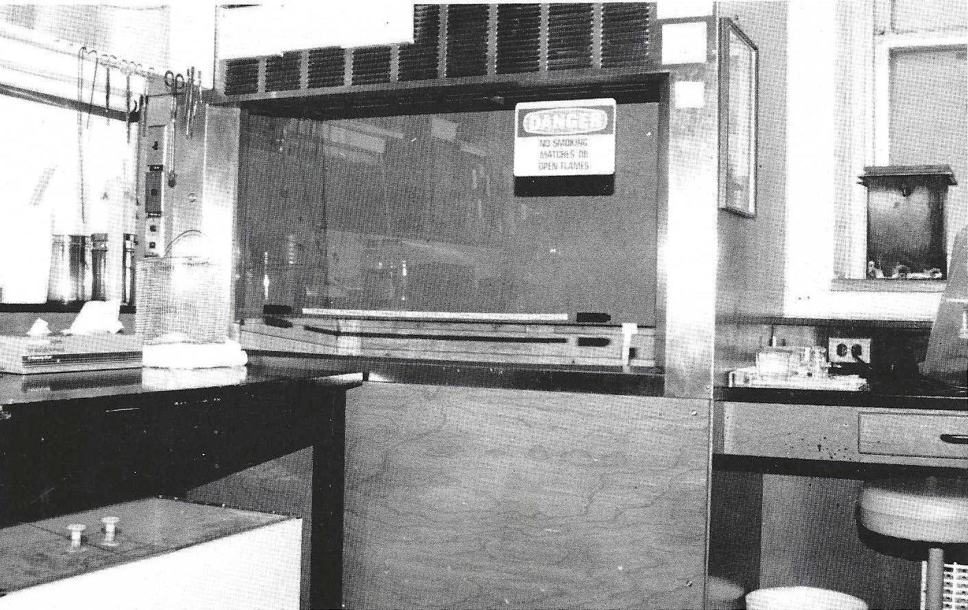
Figure 1. Rear of laboratory showing fume-hood (center) and gas cure box lower left, under the counter).
The three ingredients necessary for fire are: Fuel (the acetone), Oxygen (from the air), and Energy (sparks, flame, etc.). If one of the three is absent, then fire will not occur. Since acetone is recommended in the S-10 procedure, and air is all around us, the best alternative was to remove all sources of energy. This premise guided our design. We were fortunate in having a room available which already contained a fume-hood, although extensive modifications had to be made (Fig. 1). Originally there was a large sink unit at bench level in the hood with cupboards underneath. These, along with all the water, steam and gas lines; drains; and electrical outlets were removed. Much of the plumbing, including needle valves from the gas and steam lines, were salvaged and useful when the vacuum lines were connected. A fluorescent light, inside the top of the hood and above a sheet of glass, was sealed off from the chamber using silicone caulking compound. The remainder of the cavity was also sealed so as to create a relatively air-tight box, with no potential internal sources of heat or sparks. The lower area, which had originally been cupboards, was prepared for closure with %" plywood once the freezer was installed.
SELECTION AND INSTALLATION OF FREEZER
If flammable fluids are stored in a refrigerator or freezer, these appliances should be "explosion-proof in the sense of having all potential ignition sources located outside the cabinet. However, if the vapors can escape from the freezer and sink to floor-level (acetone vapor being heavier than air), then the potential for fire or explosion continues to exist if the vapors come in contact with other sources of heat or flame which are inherent in most laboratories. Therefore, unless the whole laboratory is made explosion-proof, an explosion- proof freezer does not necessarily solve the explosion problem. In fact, a modified commercial freezer, under the conditions outlined below, is safer than the more expensive "explosion-proof type.
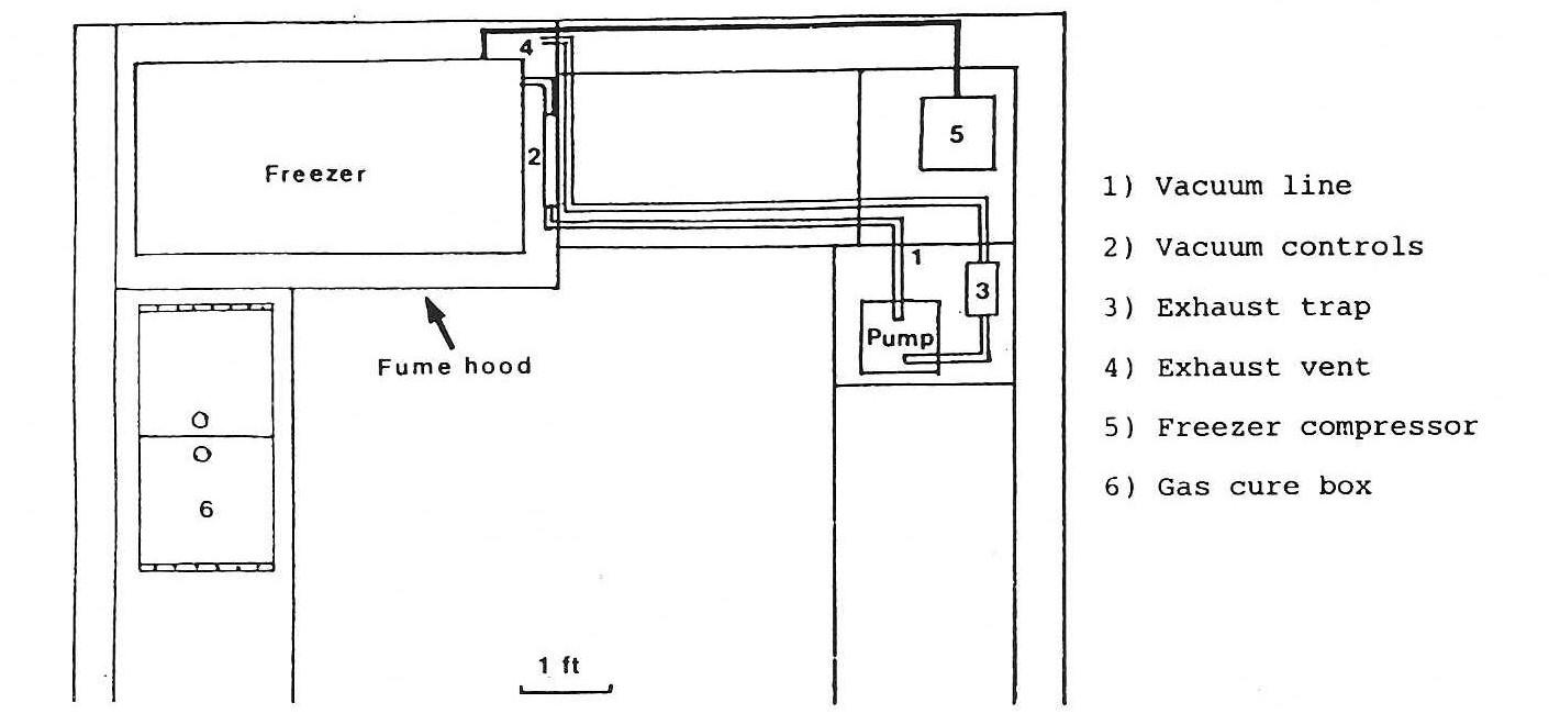
Figure 2. Schematic of rear area of laboratory (See Fig.1).
After reviewing various quotes, a 13 cu. ft. freezer, 23"W x 51 "L x 36"H, with a remote compressor, was installed for $700.00. At the time of installation, care was taken to ensure that the thermostat was also relocated outside the fume-hood, and that all other electrical lines were disconnected (eg. warning lights). One final safety feature was to connect a ground wire to the hinges of the freezer to reduce the possibility of static build-up. A hole (V diam.) was drilled through the wall of the freezer, using care not to damage any cooling pipes hidden in the wall of the freezer. A tygon vacuum line was fed through the hole and the hole around the tubing was sealed with silicone caulking compound. It is important to modify the freezer before it is placed in the fume-hood and connected to the compressor, after which it is difficult to move.
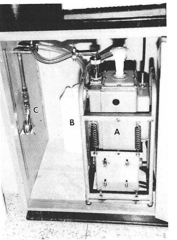
Figure 3. Vacuum pump located underneath the counter. A - pump, B - Oil trap for exhaust, C - Drain in Vacuum line.
PUMP AND VACUUM LINES
Two inherent problems associated with the use of a vacuum pump are: 1) the motor is a source of ignition and 2) the exhaust contains acetone vapor.
Therefore, the vacuum pump and freezer compressor were located four feet from the fume-hood (Fig. 2). The vacuum pump (Fig. 3) was taken from an out-dated Hitachi electron microscope which was no longer in use. The vacuum and exhaust lines were located underneath the counter as they run from the pump to the hood. Note that the exhaust from the pump ends up in the fume- hood, where the vapors are safely vented. The vacuum control unit is mounted inside the hood on the right side, about 18 inches above the freezer (Fig. 4). The vacuum lines were made from %" copper water pipe, with soldered joints (Rumph, 1987). Using the salvaged pipe, joints and valves from the old fixtures, the cost of the vacuum control unit was minor (approximately $50.00).
The Bennett manometer, an additional but essential expense, was connected with tygon pressure tubing, as was the final connection to the freezer.
GAS CURE CHAMBER
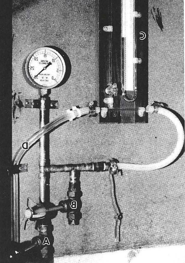
Figure 4. Vacuum control unit. A - Shut-off valve, B - Vacuum control valve, C - Bennert manometer, D - Tubing to freezer.
The primary safety consideration with the gas cure chamber, is the ability to disperse the fumes that escape when the lid is opened to manicure the specimens. Initially, we considered using an old incubator, laid on its back. This proved to be awkward and utilized a great deal of space. A box 36"L X 18"W X 24"H was constructed from arborite coated chip-board (the same as a kitchen counter-top) and the top was closed with a hinged, transparent, V. thick acrylic plastic top (Fig. 5). The box was relatively air-tight and was mounted on castors for easy movement. Cost of materials and labor was $350.00. The plastic-coated wire baskets that had come with the freezer were modified and used to make shelves for specimens in the gas cure box. When curing specimens, the box was stored under the counter. When manicuring specimens or opening the box for any other reason, it can be moved out to the front of the fume-hood. By opening the glass front of the fume-hood about 6 inches, a draught is created which is sufficient to draw up any gas from the opened curing box. We have found this to be sufficient to keep the rest of the room free from fumes.
SOME ADVICE ON HOW TO START:
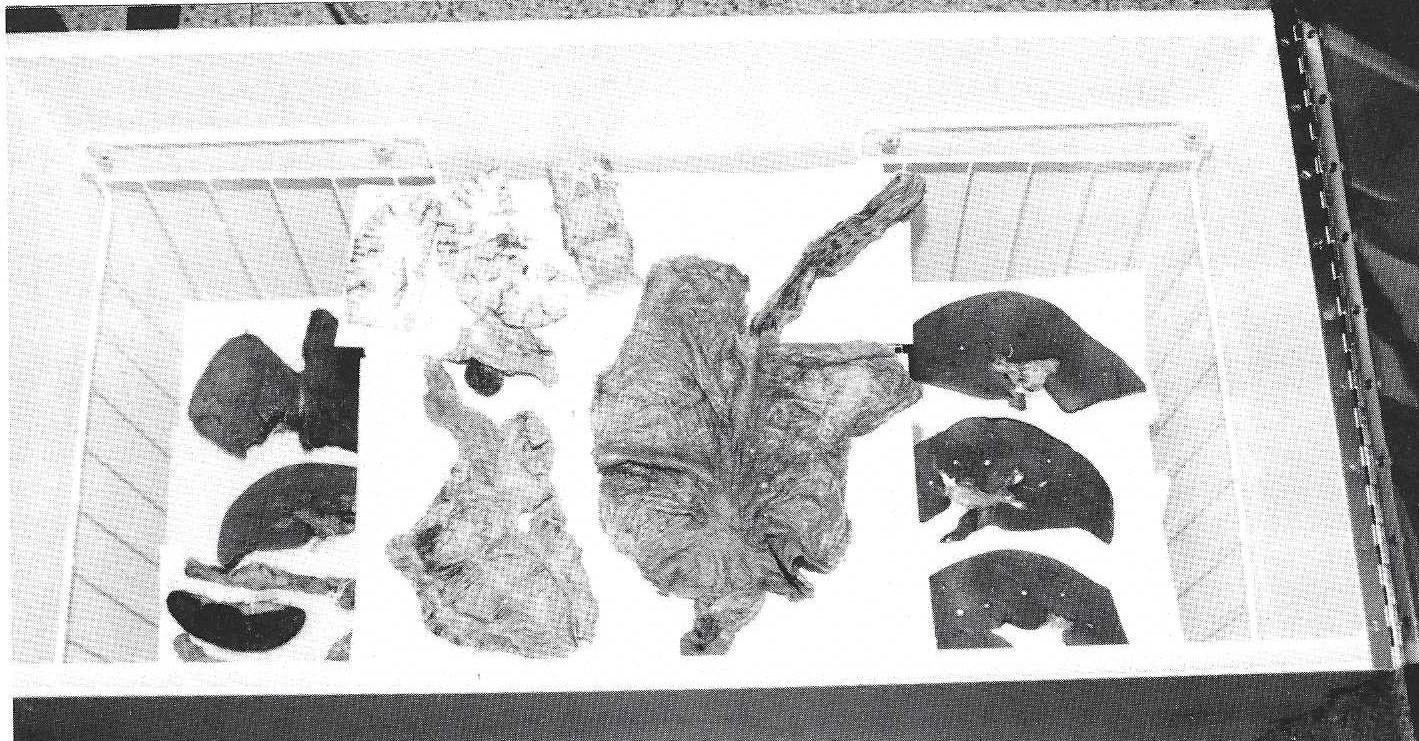
Figure 5. Gas cure box with assorted specimens. Note hinged lid (arrows) on each end.
ACKNOWLEDGEMENTS:
I would like to thank Dr. Robert Kisilevsky, Professor and Head of the Department of Pathology, for his interest and support in establishing this laboratory. My thanks also to Gerhard Penz for allowing me to visit his laboratory and introducing me to the basics of plastination. Finally, thanks to Lloyd Kennedy for taking the photographs for this paper.
Rumph, PF, PD Garrett, AE Marshall: A versatile control system for plastination. J Int Soc Plastination Vol 1(2):4-8,July, 1987. https://doi.org/10.56507/IZLI7746
von Hagens, G: Heidelberg Plastination Folder: Collection of all technical leaflets for plastination. Anatomisches Institut 1, Universitat Heidelberg, 1985.