1-Institute of Pathology, City Hospital, Munchen-Schwabing, 8000 Munchen, GERMANY
2-Institute of Anatomy Medical Faculty, The Humboldt-University of Berlin, Philippstrasse 12, 0-1040 Berlin, GERMANY
For six years, the S 10-standard- plastination-technique has produced beautiful brain specimens in Munchen. Methods of preserving and highlighting the arterial vascular supply of the human brain have been studied (Riepertinger, 1988; 1989). BIODUR E 20 (red) was selected to fill the arteries to assist medical students in studying the vessels of the brain. Previous work "Fixation of the brain for plastination- special considerations", presented in 1986 at the 3rd International Plastination Conference in San Antonio was modified. I t was concluded from previous experiments (Riepertinger, 1988) that to inject the brain specimens in situ, yields the best specimen. In situ injection negates the possibility of injuring the smallest vessels, as happens when the brain is removed in the fresh state. Furthermore, optimal anatomical shape is preserved by prefixation, as well as the other organs in the cranial cavity are injected. The disadvantage of this method is: no visual control of the degree of filling of the brain vessels with BIODUR E20 is afforded. Therefore, vascular ruptures, caused by excessive injection pressure, and brain disease can not be recognized until the brain is removed.
E20; Injections: Silicone
Alfred Riepertinger Institute of Pathology, City Hospital, Munchen-Schwabing, 8000 Munchen, GERMANY

![]()


For six years, the S 10-standard- plastination-technique has produced beautiful brain specimens in Munchen. Methods of preserving and highlighting the arterial vascular supply of the human brain have been studied (Riepertinger, 1988; 1989). BIODUR E 20 (red) was selected to fill the arteries to assist medical students in studying the vessels of the brain. Previous work "Fixation of the brain for plastination- special considerations", presented in 1986 at the 3rd International Plastination Conference in San Antonio was modified. I t was concluded from previous experiments (Riepertinger, 1988) that to inject the brain specimens in situ, yields the best specimen. In situ injection negates the possibility of injuring the smallest vessels, as happens when the brain is removed in the fresh state. Furthermore, optimal anatomical shape is preserved by prefixation, as well as the other organs in the cranial cavity are injected. The disadvantage of this method is: no visual control of the degree of filling of the brain vessels with BIODUR E20 is afforded. Therefore, vascular ruptures, caused by excessive injection pressure, and brain disease can not be recognized until the brain is removed.
The process for preparing injected brains was divided into the following steps:
To obtain an excellent specimen, it is necessary to follow all steps carefully.
1.SELECTION OF THE CORPSE:
Specimen preparation must commence within 48 hours after death. If possible the deceased should not be older than 70 years and have no brain disease including apoplexy and arteriosclerosis.
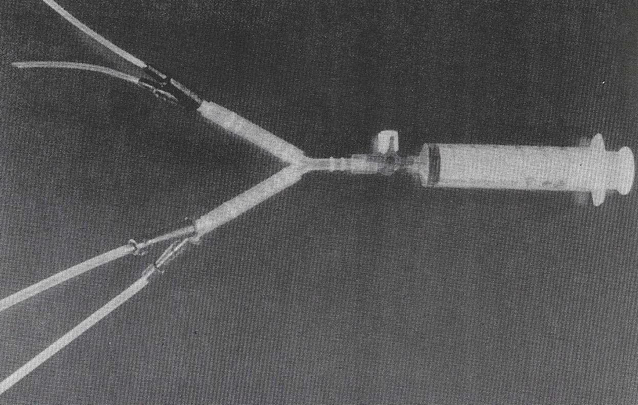
Figure 1. Four-way injection system for injection of the E20 reaction mixture.
2. EXPOSURE OF ARTERIES SUPPLYING THE BRAIN:
To assure optimal, uniform color injection of the arterial system of the brain, all four arteries supplying the brain must be injected at the same time. Therefore, a 4- way-injection-system (Fig. 1) was prepared prior to specimen injection. It consisted of two pieces of 2.5mm tubing, 7cm long (suprapubic bladder drainage set) for the vertebral arteries and two pieces of 4mm, tubing 12cm long (suction straight with funnel) for the internal carotid arteries. In preparation for injection, the thorax was opened to expose the two subclavian arteries and hence isolation and cannulation of the vertebral arteries (Fig. 2). The two common carotid arteries and jugular veins were exposed in the neck and followed superiorly to their bifurcation into the internal and external carotid arteries (Fig. 2). Both right and left internal carotid arteries and right and left vertebral arteries were cannulated and the cannulas ligated in place. Then both external carotid arteries were ligated (Fig. 3).
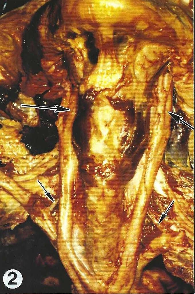 Figure 2. Exposure of the internal carotid (large arrows) and vertebral arteries (small arrows). |
 Figure 3. Cannulas are ligated in place in both the internal carotid (larger tubing) and vertebral arteries (smaller tubing) for injection of the E20 reaction mixture. |
3.RINSING WITH PHYSIOLOGICAL SALINE:
Rinsing of the vessels of the brain with saline expanded the arteries and rinsed the blood out. A balloon pump (hand-operated air pressure) produced the desired pressure for perfusion of the saline. Rinsing was continued until no blood flowed from the veins of the throat which had been opened during preparation. Between 1 and 2 L of saline solution was required for the rinsing process.
4.PREFIXATION with 10% FORMALIN:
Following the saline rinse, prefixation was done by perfusing 1 to 2 L of 10% formalin, under moderate pressure, into the brain via the cannula system. Prefixation dilated the major arteries of the brain preparing them for optimal filling with the E20 plastic and hardened the brain in its natural shape. When injection was completed, the injection-system was closed allowing the formalin to react with the brain tissue for three hours before E20 injection.
5.INJECTION WITH BIODUR E 20 RED:
Three hours after completion of the formalin injection, the E20 reaction mixture was prepared by mixing together: 25 g E20 (red), 11.2 g Hardener E2, and 5 g Plasticizer AE10 (von Hagens, 1985). For brain injection, the thinner, ethyl methyl ketone was not used in order to maintain a viscous consistency and assure that only the larger arteries were filled. A 3-way- stopcock, into which a 30ml syringe could be attached, was connected to the injection tubing assembly (Fig. 1). Using steady moderate pressure, 40ml of the E20 reaction mixture was injected slowly into the arteries. 40ml of E20 was an adequate volume to fill the major arteries of the brain. After injection, the 3-way-stopcock was closed and the corpse was kept at +5°C overnight. The brain was removed from the corpse the next day. Since polymerization of the E20 is slowed by cool temperature, the injected vessels could be transected easily when the brain was removed. The partially cured plastic has a doughy-tough consistency.
6.REMOVAL OF BRAIN:
A surgical circular saw (cast cutter), with a blade diameter of 5cm, was used for sawing. A spacing stop shim was placed on the saw blade to restrict the maximum depth of incision to 4 mm (Riepertinger, 1988). The skull cap was incised and removed from the base of the skull using a circular incision. Caution must be exercised when cutting open the skull, since thickness varies. The saw chips provided information on the depth of the incision,
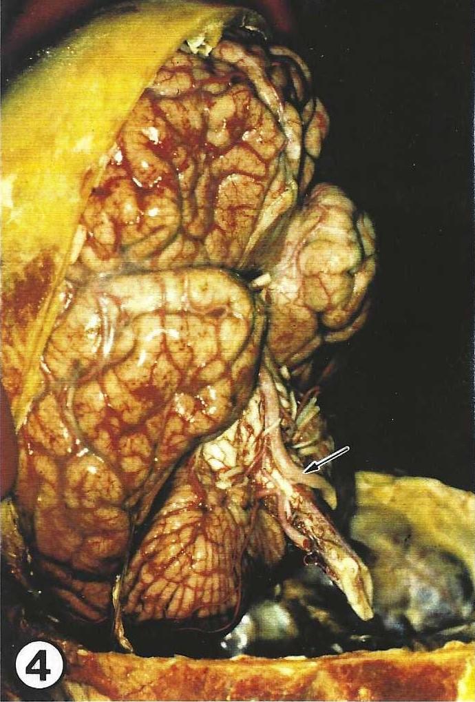
Figure 4. E20 injected brain lying in its skull cap. Injected basilar artery (arrow).
superficial bone chips were white and the deeper chips were red. A cross-chisel was inserted in the incision every 2 cm to lift and loosen the skull cap. Once loosened, the skull cap was carefully removed (Fig. 4). The dura mater was lifted and removed from the brain hemispheres using surgical forceps. During removal, the occipital lobes of the cerebral hemispheres were supported by a hand. Both poles of the frontal lobes were grasped by the other hand from the front and the side and lifted from the anterior cranial fossa. Simultaneously, the olfactory nerves were preserved and removed with the brain (Fig. 4) by lifting from the anterior base of the skull, with light pressure on the lower side of the frontal lobes. The two carotid arteries (filled with E20), the optic nerves, as well as the pituitary stalk were cut free as close to the bone as possible. Next, the two temporal lobes were removed from their fossa using digital manipulation. Now the tentorium cerebelli can be seen and was opened with a long, pointed knife directed along the tentorium ossium. Cranial nerves V-VIII were resected. Digitally the cerebellum was gently pushed away from the petrous temporal bone. The pointed, long knife was directed parallel to the medulla into the foramen magnum and the spinal cord along with the two vertebral arteries were severed as long as possible. Aided by the spread index and middle fingers, the cerebellum and medulla were carefully rolled out of the posterior cranial fossa. The brain was placed into fixative.
7.FIXATION:
A formalin-sugar solution was used to fix the brain by immersion. Three liters of 5% formalin solution with 400g of refined crystal sugar added was used per brain. Addition of sugar causes the brain to float. Thus suspension by the basilar artery, which often leads to kinks in the vessels, was not necessary. The sugar solution enhances differentiation of gray and white matter. After a week of immersion fixation in the formalin-sugar solution, the brain was rinsed in tap water for 30 minutes and the specimen checked for symmetry (roundness laterally) of the cerebral hemispheres. The brain was transferred into a cold +5°C, 5% formalin solution (without sugar). After the specimen was cool fixed for 12 hours, the specimen was ready for dehydration.
8.DEHYDRATION:
Dehydration was carried out for 4 weeks in acetone. The cooled brain was placed into cold -25°C acetone with a tissue-fluid ratio of 1:10. The dehydration period in the deep-freezer was 2 weeks. At the end of the first week, the specimen was placed into fresh cold acetone. At the end of the second week, the brain was put into fresh room temperature (20°C) acetone for 2 weeks to enhance lipid extraction, from the specimen. During this period, the acetone was changed whenever it became visibly yellowish. The residual water content of the specimen was determined as needed with an acetonometer. Dehydration was ended when the acetone no longer became discolored and the residual water content remained less than 2%. To prepare for forced impregnation, the specimen was placed in fresh precooled acetone ( + 5°C).
9.FORCED IMPREGNATION:
The brain specimen required 3 weeks of impregnation at -25 °C following the standard S10 procedure (von Hagens, 1985). The specimen was placed into the polymer mix (S10/S3) and allowed to remain overnight to equilibrate. Vacuum was gradually increased one atmosphere.
When impregnation was completed, the vacuum kettle was aerated and the specimen remained in the polymer-mix at atmospheric pressure overnight to relieve tension. It was beneficial to end impregnation on Monday so that the entire week was available for the first phase of gas cure which is labor intense.
10.HARDENING:
W hen forced impregnation was completed, the specimen was removed from the vacuum kettle and excess polymer drained back into the kettle. The brain was placed on a slanted surface which was covered with air pad

Figure 5. E20 injected brain after plastination. Basilar artery (arrowhead), Internal carotid arteries (arrows).
foil (bubble packing sheets), so that the S10 residue dripped off for around 5 hours at a room temperature. The specimen was then wiped with paper towels and laid onto grids covered with filter paper in the gas chamber for hardening for 3 weeks. S 6 (gas cure) was rapidly volatilized using a membrane (aquarium) pump and an aquarium stone. The stone caused increased bubble formation of the gas hardener and resulted in an atmosphere rich in gas cure vapor. Calcium chloride was placed in the gas chamber to absorb excess moisture. During the first two days of curing, the specimen was checked every hour and oozing polymer was wiped off with paper towels. The specimen was removed each night from the gas chamber and replaced in the morning when it could be manicured. Once the surface of the brain had hardened (approximately 5 days), the specimen was inspected daily for oozing. When no oozing polymer was observed on the specimen, it was ready for final cure and was sealed in polyethylene foil (plastic wrap) for 4 weeks. At the end of the long plastination process, a highly detailed injection specimen of the human brain (Fig. 5) was finally available for instruction and research. These specimens are superior to existing specimens or aids.
Riepertinger, Alfred: Fixation of the human brain for plastination: Special considerations. J Int Soc Plastination 2(1):8-12, 1988.
https://doi.org/10.56507/XMBX2600
Riepertinger, Alfred: Plastination of the brain with attached spinal cord. J Int Soc Plastination 3:22-28, 1989.
https://doi.org/10.56507/JGJS6881
von Hagens, Gunther: Heidelberg Plastination Folder: Collection of all technical leaflets for plastination. Anatomisches Institut 1. Universtat Heidelberg, 1985.