1- Plastination Laboratory, Centre for Anatomy and Cell Biology, Plastination and Topographic Anatomy, The Medical University of Vienna, Wahringerstr. 1313, A-1090 Wien, Austria.
2- Human Anatomy Laboratory, Department of Anatomy with Radiology, School of Medicine, University of Auckland, New Zealand.
Since its development 30 years ago, plastination has become the best method for preservation of perishable biological human and animal tissue. In recent years, plastination has been utilized in the study of different anatomical and clinical questions. Using the Biodur® E12 technique, transparent tissue slices are produced which exhibit detailed structures in their normal anatomical position, especially regarding muscular, vascular and interstitial tissue. The Biodur® El2 method of plastination is used to create 2-5mm transparent slices. Many modem diagnostic techniques including radiography, computed tomography, magnetic resonance imaging and ultra sound underscore the importance of understanding serial sectional anatomy of the body. The Biodur® E12 plastination method allows production of precise transparent sectional preparations of superb visual clarity. These sections allow visualization of gross structures as well as submacroscopic structures with the naked eye. Further study of E12 sections at the histological level is also possible with the use of light microscopy and electronic video equipment.
plastination; epoxy; E12; E1; AE30; AE10; slices; body
M-C. SORA - Plastination Laboratory, Centre for Anatomy and Cell Biology, Plastination and Topographic Anatomy, The Medical University of Vienna, Wahringerstr. 1313, A-1090 Wien, Austria. Telephone: 43-1-4277-611-50; Fax: 43-1-4277-611-70; E-mail: mircea-constantin.sora@meduniwien.ac.at

![]()


Today's modem diagnostic imaging techniques (computed tomography, magnetic resonance imaging, and ultrasound) underscore the importance of understanding sectional anatomy of the human and animal body. The purpose of E12 sheet plastination is to preserve 2-5mm slices of tissue for examination/study by replacing all tissue fluid and a significant amount of fat with a curable resin. The Biodur® E12 plastination method provides accurate, precise and semi-transparent sectional preparations which offer superb visual clarity of gross structures down to a submacroscopic level viewable with the naked eye.
Body slices (2-5mm thick) are produced using a flat chamber or a sandwich technique. The E12 method is named for the epoxy resin Biodur® E12 used for this process . As in other plastination methods, water and some lipid are removed from the slices and replaced with the curable epoxy resin-mix. Chemicals used in epoxy-plastination include acetone, epoxy resin, epoxy hardeners, and epoxy plasticiser.
Two techniques for producing E 12 impregnated slices are: The sandwich technique and The flat chamber technique. As with other methods of plastination, the standard Biodur® E12 technique may be modified by omitting or changing procedural steps. However, in order to obtain the best results, the standard description of the Biodur® E12 technique should be followed.
Teaching with clinical correlation as well as having powerful research potential are the hallmarks of this exciting technique. This standard protocol describes plastination of sliced body parts via the E12 method .
The standard steps of Biodur® E12 plastination are specimen preparation, cold dehydration , degreasing, impregnation and curing (von Hagens, 1986; Fasel et al., 1988; Weber and Henry, 1993; Cook, 1996; Cook and Ali-Ali , 1997; An and Zhang, 1999; Sora et al., 2002; Sora et al., 2004).
The general protocol for production of E12 - epoxy (2-3mm) slices is found in table 1 for the frozen specimen (-75°C).
Specimen preparation
The desired specimen is selected and may or may not be fixed with formalin. Fixation is not necessary for production of semi-transparent body slices using El2 plastination. In general it is desirable that tissue be fixed to prevent any potential biohazard risk which may accompany handling and sawing of human or animal tissue. The disadvantages associated with tissue fixation are a marked loss of tissue color and an increase in the freezing point of the specimen. The specimen should be positioned in proper anatomical position prior to fixation.
It is important to freeze the portion of the body chosen for sectioning at -75°C, especially if the tissue was fixed. If unfixed tissue is being used, the specimen should be placed in proper anatomical position prior to freezing. Shock freezing at -75°C is necessary to reduce the formation of ice crystals. Common freezers which achieve -25°C are not ideal because ice crystals may develop in the tissue during freezing and the harder the specimen is frozen the better slicing will be. Pre-cooling of specimens to +5°C overnight prior to freezing can help prevent ice formation . Specimens need to be frozen uniformly. Therefore, keep the specimen in the deep freezer for five days to assure complete freezing. Large specimens should be subdivided for ease of handling and to avoid defrosting of the specimen during slicing. For example, a torso should be divided into several parts prior to producing slices from each part. Hairy specimens should have the hair clipped prior to sectioning.
Sawing: Body slices (large or small) can be sliced on a butcher band saw. Smaller specimens are technically easier to saw. The band saw should have a guide stop and be constructed of stainless steel for easy cleaning and maintenance . A saw with a cooled guide stop is beneficial but not essential. Cooling the guide stop for at least two hours at -25°C will help prevent thawing of
the slices and the specimen. The ideal slice thickness is 2-3mm which assures a transparency of the connective tissue in the finished specimen. Sections greater than 3mm in thickness are typically too dense and contain many superimposed structures which substantially diminish clarity. For best results, band saw speed should be 20-35m/sec. Slices may be cleaned of sawdust for immediate processing or be stored between polyethylene foil in a deep freezer for later use.

Figure 1. Fresh tissue slice with saw dust, lying on metal grid.
Saw dust removal: Freshly sawn slices are usually covered with a thick layer of tissue shavings on each side (Fig. 1). These tissue particles must be removed because they will appear as artefacts on the finished product. This saw dust may be removed by scraping the slices while frozen, either before or after immersion in cold acetone. Flushing the surface with a small cool stream of tap water while frozen or brushing them in the last dehydration bath at room temperature or any combination of the aforementioned methods as is deemed suitable by the investigator are acceptable . Any of these methods have some disadvantages ; therefore there is no ideal method . The recommended method is to scrape the dust off using a scalpel or sharp broad knife while frozen in the freezer. To do this, the slice is placed on a cold 1Omm metal plate, which has been cooled for several hours at -25°C. Using the edge of a length of Perspex (Plexiglas) to scrap the frozen tissue may be a less hazardous method than using a scalpel since it is passed gently over the surface in a single sweeping movement. Also, the slice may be submerged in -25°C acetone to prevent defrosting of the slice. The dust can then be scraped from the surface of slice while they are frozen and submerged. Brushing the slices in the last dehydration bath is more difficult and not easily done if slices contain intestinal loops or other small pieces. If a stream of water is used, it must be done quickly to avoid thawing of the slice. The cleaned slices are then placed on acetone resistant grids and submerged in cold (-25°C) acetone.
Dehydration and degreasing
The standard dehydration procedure for plastination is freeze substitution. During freeze substitution, specimens are submerged in cold (-25°C) acetone (technical grade) and immediately freeze upon immersion thereby stabilizing the specimen's shape instantly. This method saves time and labor when compared with ethanol dehydration. In addition, shrinkage is minimal when cold acetone is used (less than 7%). Alcohol shrinkage is two to four times greater.
For all plastination methods, the use of acetone is ideal as it serves as the dehydration agent, degreasing agent and intermediary solvent and readily mixes with all the resins and polymers used for plastination .
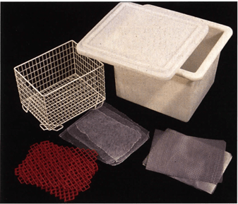
Figure 2. Accessories needed for stacking and bundling slices: Fly screen (f), grids - metal (m) and plastic (p), basket and reservoir.
To aid dehydration, fly screen (mesh) (Fig. 2) is placed between the slices. To aid transfer of slices into succeeding acetone baths, a metal or plastic grid is placed at each end of the stack and after every fifth slice for stability. The correct succession is: grid - screen - tissue slice - screen - tissue slice - screen - tissue slice etc. This arrangement permits acetone to circulate between slices and assures thorough dehydration and ease of handling. Once fifteen slices are stacked using this sequence, the slices are tied together as a bundle using string or stacked in a basket and submerged in cold acetone (Fig. 3). If many slices are prepared, baskets to contain the slice bundles allow for easier handling and changing of acetone baths.
Preferably, saw dust free slices are immersed in the first dehydration bath. If >90% acetone is available from previous dehydration baths, it may be used for this first bath. If less that 100% acetone is not available, use fresh technical grade acetone (99-100%). A recommended tissue to fluid ratio is at least 1:5-10. The basket containing the tissue slices within the screen/grids should be introduced into the acetone at an angle. This prevents trapping air bubbles within the sections, mesh and grids and permits acetone to flow evenly upwards and across the tissue surface at an oblique angle. The basket should be moved from side to side as an additional measure to remove trapped air bubbles. The submerged slices need to be adequately covered with acetone.
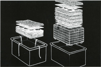
Figure 3. Slices ready to be bundled and tied with twine or placed in basket.
Likely three acetone baths will be necessary. The thin slices and separation by screen will allow the slices to dehydrate in seven to nine days. After three days in the first bath, acetone is changed for new/fresh acetone, #2 bath (Fig. 4). Specimens should be transferred quickly from bath to bath and not allowed to dry. Dried areas will show up later as white patches of shrinkage in the finished product. After three days in bath #2, the specimens are transferred into bath #3. It is good to check acetone purity of bath #2. This will assure complete dehydration or if bath #3 is necessary . The acetone should be stirred and make sure acetone temperature is the same as the calibration temperature of the acetonometer. Most acetonometers are calibrated at +15, +20, or -10°C. To obtain an accurate reading, acetone must be brought to the calibrated temperature before reading the purity. If acetone concentration is at least 98.5%, dehydration is complete and bath 3 is not necessary . If acetone purity is <98%, the specimens need to be transferred into bath #3. The acetone concentration should be checked at the end of bath #3 (day 11) and conclusions on the extent of dehydration are determined. If dehydrated thoroughly, the slices are ready for degreasing.
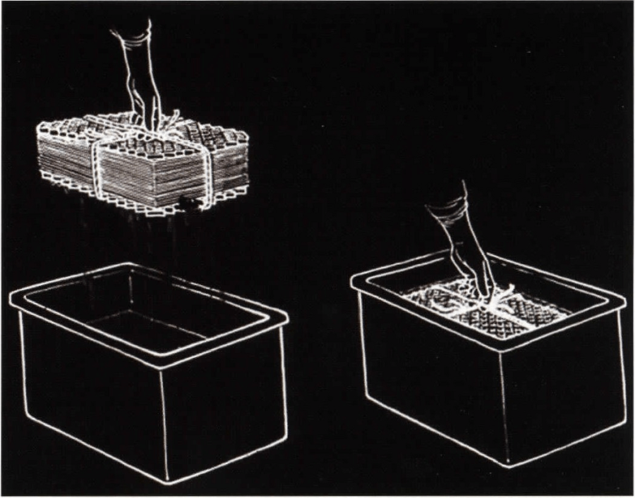
Figure 4. Changing bundled slices into new acetone bath.
The last dehydration bath, with a final concentration of at least 98.5%, is brought to room temperature to start the degreasing process. Degreasing is a vital step for production of good slices using E12 methodology. If specimens do not contain much fat, acetone is usually adequate to assure enough lipid removal. Lipid extraction from the specimen is essential to create transparency and good definition between structures of the E12 impregnated slice. When the acetone has turned yellow, the specimens must be transferred through one or two more room temperature acetone baths. Usually a minimum of two weeks and two or three acetone room temperature changes are needed. However, many slices contain high amounts of lipid and need a much stronger lipid remover. Hence after dehydration bath #3, these specimens are transferred into methylene chloride [dichloromethane (MeCl)]. MeCl is the ideal fluid for degreasing. MeCl is a hazardous substance and must be handled and kept in a ventilated hood. There is no method to measure the fat concentration of the used MeCl or acetone. Therefore, the color of the acetone/MeCl baths must be monitored for color change to yellow. When the color becomes an intense yellow, the bath is changed. MeCl degreasing takes less than one week, with one mid-week change to new MeCl. To assure adequate degreasing, it is necessary to visually inspect the quality of the degreased slices.
Forced Impregnation
Farced impregnation is the central and very important process in plastination. During impregnation , the solvent is extracted from the cellular and interstitial space of the slice and is replaced with the resin impregnation-mix. The epoxy resin and hardeners are mixed as follows to prepare the E 12 impregnation mixture: E12 - 95pbw, AE30 - 5pbw, AE l O - 20pbw, El - 26pbw. The epoxy reaction-mixture has a relatively short pot life which cannot be extended by freezing as with the silicone reaction-mixture. At freezing temperatures , E12 crystallizes and becomes too viscous for exchange in the cold. Crystallization of the E 12 resin may also occur during routine storage prior to adding hardener. Storage crystallization can be reversed by warming the resin to 80°C. However, it must cool to room temperature before the hardener is added.
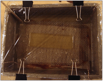
Figure 5. Impregnation bath with thermometer in corner and covered with foil.
Only enough volume of reaction-mixture is prepared to adequately cover the intended volume of slices for impregnation. Larger quantities of resin reaction mixture cure faster. Therefore, the specimen impregnation reservoir size should be planned to minimize an excess space around the perimeter of the stack of the slices. The reaction-mixture is placed in the impregnation vat in the room temperature or +S°C vacuum kettle. The dehydrated and degreased slices are transferred from the degreasing bath (MeCl or Acetone) into the impregnation bath. The bundle of stacked slices and screens are rapidly submerged (to avoid drying of the slices) into the impregnation bath. The stack of slices tends to float and must be weighted down or held down by the basket lid. If MeCl is used, transfer should be done in a ventilated hood. A safety level of resin of at least 3-Scm over the top of the slices is necessary . Lining the vacuum chamber and covering the impregnation reservoir with plastic foil/wrap ensures easy clean up of the splashing epoxy (Fig. S). A thermometer is placed in the vacuum kettle (Fig. 5).
The vacuum pump is turned on, prior to applying vacuum for 10 minutes, to allow the pump to warm to working temperature. The box containing the tissue slices and the E12 impregnation-mixture is placed in the vacuum chamber, at +S°C or room temperature (RT). Once the vacuum kettle has been prepared , vacuum is applied and the kettle is sealed. The rate of lowering pressure and hence extraction of solvent is rapid. Pressure is continuously reduced, but slowly, starting at atmosphere (76cm Hg) down to 2mm Hg over nearly two days. The volatile intermedium has a low vapor pressure and the resin-mix a high vapor pressure. Therefore as pressure is lowered and the solvent boiling point is reached, the volatile intermedium vaporizes and bubbles out of the specimen into the resin and is extracted out through the pump exhaust. However , in the first two hours as pressure is decreased frequently, only air is evacuated until the boiling point of the solvent is reached. At +S°C, 8.Scm Hg pressure acetone commences to vaporize and hence impregnation begins. This is the suggested pressure level to be reached after the first two hours of vacuum . With methylene chloride (MeCl), the two hour goal is to reach 18cm of pressure (MeCl's vapor pressure). Respectively , at RT their vapor pressures are 18cm and 3Scm Hg (Pereira Sampaio, 2006).

Figure 6. Impregnation bubbles being produced at an appropriate rate.
Solvent bubbles will usually be a bit smaller than the air bubbles. The goal for the end of day one: Decrease pressure from atmosphere (76cm) to Scm Hg for either solvent (acetone or MeCl). As pressure is decreased below the solvent's vapor pressure, the acetone or MeCl vigorously boils out of the slices and lowers the temperature of the resin, which helps to control the exothermicity of the reaction-mixture (Fig. 6). Rate of impregnation (decreasing pressure) is monitored by formation of impregnation bubbles rather than relying solely on the vacuum level indicated by the manometer. Frequent regulation of the rate of evacuation is necessary to keep the impregnation boiling rate proper and hence keeps the temperature regulated between 0°C to 10°C which is the best range. Excessive bubble formation is an indicator of impregnating too fast. Resin level must be observed and more reaction-mixture added when necessary to keep the slices submerged.
Because of the variation of tissue volume and variation of impregnation-mixture volume used, it is not feasible to prepare a standardized vacuum curve for forced impregnation. However, it is beneficial to record vacuum adjustments and corresponding vacuum levels as well as the resin temperature to aid future projects and as a safety check on the current load if the impregnation cycle is interrupted. If impregnation conditions are kept constant, these data may facilitate the control of further impregnation runs.
By the end of the first day, the pressure should be reduced to 5cm Hg and during the second day, the pressure is decreased continuously down to 2mm Hg (at least 5mm Hg). When bubbling decreases considerably and big bubbles appear on the resin-mix surface and splash, impregnation is complete. Note: Bubbling may not completely stop. The best indicator that impregnation is complete is an increase of reaction mixture temperature . Initially, impregnation temperature will decrease continuously, but at some point it will begin to rise. Standard impregnation takes 36-48 hours at +S°C. The elasticizer (AE10) in the impregnation-mixture increases the pot-life of the resin mix. Impregnation at room temperature usually will be finished in 32 hours.
After impregnation is completed, the chamber is returned to atmospheric pressure and the glass port opened. The box containing the slices is removed and the foil/liner is discarded.
Curing

Figure 7. Impregnated slices draining of excess El2 resin
mix
After impregnation is completed, the bundle containing the slices, grids and screen is lifted from the E 12 impregnation-mixture and the excessive E 12-mix drained (Fig. 7). There are two methods to cure E12 slices: The flat chamber method (using glass plates) and the sandwich method (using heavy foil sheets) both use the following casting-mixture: E12 - 9Spbw, AE30 - Spbw, E l - 26pbw (AE10 is not used in this mixture to avoid soft flexible slices).
Casting slices in flat chambers: Flat chambers are assembled from 3mm thick safety glass plates, appropriate diameter gasket (silicone tubing or gasket or PVC gasket) and fold-back clamps (Fig. 8). To make a leak proof 3S x 4Scm flat chamber, 10 fold-back clamps (3 on each side, 4 at the bottom and evenly spaced) are needed for silicone tubing. If other gasket material is used, more clamps are necessary for a good seal: 20 clamps for silicone gasket, or 32 clamps for PVC-gasket. The length of the gasket for this size flat chamber is 150cm.

Figure 8. Flat-chamber for curing impregnated slices.
The appropriate size glass plate is placed on an assembly stand. A small pool of E12-mix is poured onto the glass plate to prevent the section sticking directly to the glass. The impregnated slice is placed on the pool of resin-mix on the glass plate . Next the silicone tubing is placed on the glass plate, 2cm from and parallel to the bottom edge of the glass. A spacer is placed in the middle of the top edge of the plate to support the top edge of the top glass which is placed into position on top of the tubing and spacer. The silicone tubing is held in position by four clamps, spaced equidistantly, starting 2cm away from each bottom comer. Next, the silicone tubing is turned upward, parallel to each side and clamps are positioned over the gasket, one each, near the top and bottom of each side and one in the middle. Consequently , all 10 fold-back clamps are placed on three sides of the flat chamber.
The flat chamber, containing the impregnated slice, is placed vertically in a supporting box so that its upper edge protrudes above the box. A flat funnel is used to fill the chamber with E12 casting-mix to about 8cm below the top (if placed properly , the bottom edge of each top side clamp can be used as a fill indicator. The pool of E12 resin-mix added earlier will facilitate positioning the slice allowing resin-mixture to flow on both sides of the section as the chamber is filled resulting in equal distribution of resin on each side of the section. After filling, flat chambers are placed for one hour in a vacuum chamber to remove small air bubbles present in the resin. Pressure is reduced to 2mm Hg and maintained for one hour. After returning to atmosphere, any remaining bubbles are removed manually using a 1mm stainless steel hooked wire of appropriate length. After bubble removal, the specimen is aligned in the flat chamber. The chamber is placed horizontally at an inclination of 15° for at least 24 hours. During this period, the resin becomes more viscous preventing movement of slice. Finally, the flat chambers are placed upright in a 45°C oven for four days. After removal from the oven and allowed to cool down to room temperature, the glass plates are carefully removed. The epoxy slices are wrapped in foil and the sheets are cut to the desired size.
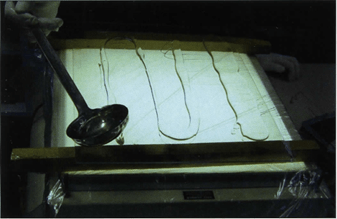
Figure 9. Sandwich curing technique: Casting-mixture poured onto heavy foil overlying the glass plate in preparation for impregnated slice.
Casting of slices using the sandwich method: This method uses heavy foil (plastic) sheets. The main difference from the flat chambers is that this method is faster. The method uses both foil sheets and glass plates. Safety glass is not required for this procedure. Window or safety glass is placed on an assembly stand and a foil sheet, which must overlap the glass plate by 2cm on all sides, is placed on the glass. Fresh and deaerated casting-mixture is poured sparingly onto the polyester foil (Fig. 9). Impregnated slices are placed on the pool of casting-mixture on the foil (Fig. 10) and casting-mixture is spooned on top of the slices. The slices are gently covered with another foil (Fig. 11) and then a spatula is used to place pressure on the foil to squeeze and remove the air bubbles from the top of the slice (Fig. 12). The foil sandwich (top and bottom foil and slice) is turned over and the foil is squeezed with the spatula to remove air on this side of the slice. If there are more slices to be cured, the process starts again with a foil and resin-mix spooned onto the foil. A slice is placed on the resin and a top foil put into place. Air is squeezed from both sides of the sandwich. This foil sandwich is placed on top of the previous foil sandwich, etc. Three foil sandwiches are placed together; then a glass plate is introduced on top of the three foil sandwiches. If more slices are ready to cure, the process starts over again on the top glass: glass I foil I slice I foil I I foil I slice I foil I I foil I slice I foil I glass I foil I slice I foil I I foil etc. (Fig. 13).
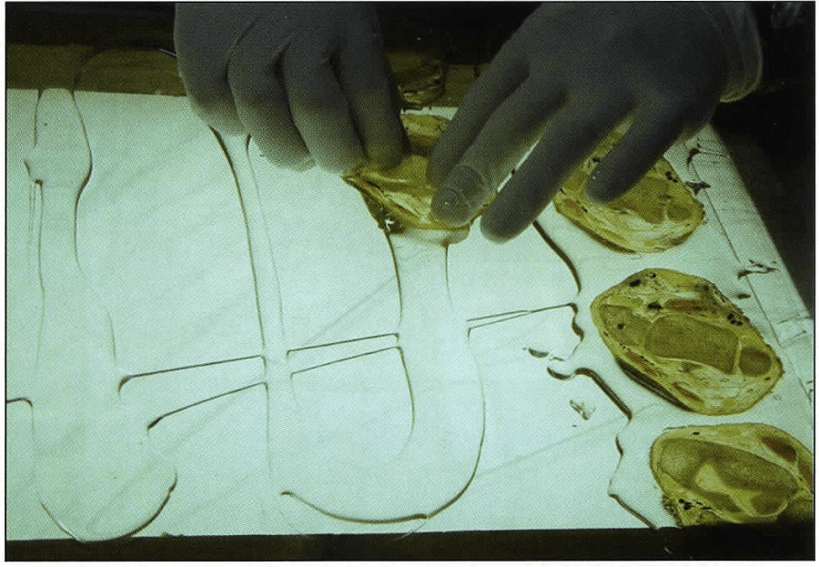 Figure 10. Sandwich curing technique: Impregnated slices placed on casting-mixture. |
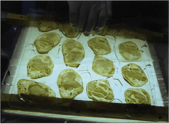 Figure 11. Sandwich curing technique: Covering slices with foil. |
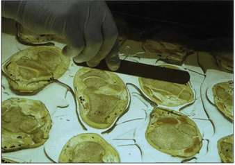 Figure 12. Sandwich curing technique: Removal of a1r bubbles using a spatula. |
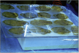 Figure 13. Sandwich curing technique: Glass is placed over foil. |

Figure 14. Sandwich curing technique: Top glass is weighted.
When the sandwich stack is finished, a glass plate is placed on the top. A tower of foil/slice/foil sandwiches is formed with glass on the top and bottom and after every 3rd sandwich, which reminds one of a sandwich. If slices are not of uniform thickness, a glass plate is only used on the bottom and the top of the stack after all of the foil sandwiches are made. This will help assure more uniformity of slices. In order to keep the foil plates pressed and to encourage excess E12 resin to ooze out, a weight is placed upon the top glass plate (Fig. 14).
This sandwich block remains at room temperature for 1 day and then is placed in a +45°C oven for four days. After the sandwich has been removed from the oven and cools to room temperature , the foil sheets are carefully removed and the resin plates containing their specimen slice are cut as desired.
| Day O | Freeze specimen -75°C. |
| Day 1 | Slice and clean sawdust from slices. |
| Day 2 | Immerse specimens in #1 -25°C acetone bath (>90%). |
| Day 5 | Immerse m #2 bath, -25°C acetone (100%). Check and record purity of bath #1. |
| Day 8 | Immerse m #3 bath, -25°C acetone (100%) Check and record purity of bath #2. |
| Day 11 | Degrease slices m Acetone or MeCl Room temperature (RT). |
| Day 18 | Impregnate in E12 resin-mix (+5°C or RT). |
| Day 20
or 27 |
Cast or sandwich slices. Lay cast 15° from horizontal at RT. |
| Day 21
or 28 |
Cure upright in + 45°C oven. |
| Day 25
or 33 |
Open flat chamber or the sandwich, cover slice with foil, saw and sand. |
The transparency and color of the plastinated El2 slices are of the highest quality. The finished El 2 sections are durable, semi-transparent and correlate readily with radiographs when placed on light boxes and above all else offer more detail than is possible with any other plastination method or gross dissection (Figs. 15-17). Successful results with the El 2 technique are dependent upon carrying out the specific parameters for section thickness, lipid extraction and impregnation technique.
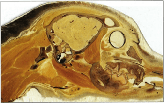 Figure 15. E12 sagittal slice of canine head. |
 Figure 16. E12 coronal (frontal) slice of human head. |
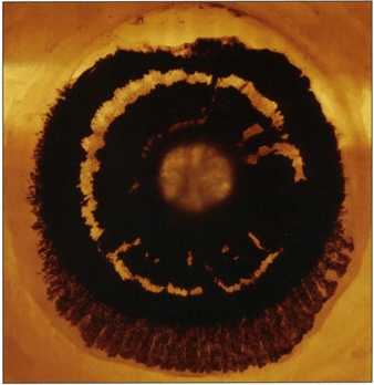 Figure 17. E12 coronal (frontal) slice of human eye. |
The main advantage of the E12 sheet plastination method is that it preserves the topography and integrity of a target region in a complete and uninterrupted state with all interconnected structures on a given plane preserved . The slices can be stored at room temperature and used later on for further investigations. Because of this, morphologic measurements can be performed easily. The data thus obtained are comparable to that of high quality magnetic resonance (MR) images (Beyersdorff et al., 2001; Steinke, 2001; Thomas et al., 2003). The one slight disadvantage is: epoxy slices tend to yellow in color over a period of years.
The removal of lipid content from tissue slices prior to impregnation is an essential step for the success of the E12 technique. Acetone, as well as being the recommended medium for dehydration by freeze substitution, serves as an adequate degreasing solvent when used at room temperature. Although not mandatory , experience demonstrates that the highest optical quality for El2 sections was achieved from tissue sections that had been degreased first in acetone at room temperature and then transferred to methylene chloride for more lipid extraction.
For research these slices allow topographical study of all body structures in an uncollapsed and non-dislocated state. Also, specimens are useful in advanced sectional topography programs and resident training in CT and MR. Computerized reconstruction of anatomical structures is becoming useful for developing anatomical and research teaching modules and animations. E12 slices will likely play a significant role in these areas.
An P-C, Zhang M. 1999: A Technique for Preserving the Subarachnoid Space and its Contents in a Natural State with Different Colours. J Int Soc Plastination 14(1)12-17.
https://doi.org/10.56507/CQUW3856
Beyersdorff D, Schiemann T, Taupitz M, Kooijman H, Hamm B, Nicolas V. 2001: Sectional depiction of the pelvic floor by CT, MR imaging and sheet plastination: Computer-aided correlation and 3D model. Eur Radiol 11(4):659-64.
https://doi.org/10.1007/s003300000561
Cook P. 1996: Plastination as a Clinically Based Teaching Aid at the University of Auckland. J Int Soc Plastination 11(1):22.
https://doi.org/10.1159/000147907
Cook P, Al-Ali S. 1997: Submacroscopic Interpretation of Human Sectional Anatomy Using Plastinated E 12 Sections. J Int Soc Plastination 12(2):17-27.
https://doi.org/10.56507/XICY2283
Fasel J, Mohler R, Lehmann B. 1988: A technical note for improvement of the El2 technique. J Int Soc Plastination 2( 1):4-7.
https://doi.org/10.56507/LNBR6798
Pereira-Sampaia MA, van Horst C, Marques-Sampaia BPS, Smodlaka H, Favorito LA, Sampaia FIB, Henry RW. 2006 : Theoretical considerations and preliminary studies on alcohol as an intermediary solvent. Abstract presented at The 13th International Conference on Plastination - Vienna, Austria, July 2 to 7, 2006. J Int Soc Plastination 21 :27-28.
Sora MC. 2006: Principles of epoxy plastination technique (E12). Abstract presented at The 13th International Conference on Plastination - Vienna, Austria, July 2 to 7, 2006. J Int Soc Plastination 21:9-10.
Sora MC. 2006: Principles of epoxy (E12) plastination technique. Abstract presented at The 13th International Conference on Plastination - Vienna, Austria, July 2 to 7, 2006. J Int Soc Plastination 21:25-26.
Sora MC, Brugger PC, Strobl B. 2002: Shrinkage during El2 Plastination. J Int Soc Plastination 17:23- 27.
https://doi.org/10.56507/DIUH4490
Sora MC, Strobl B, Staykov D, Forster-Streffleur S. 2004 : Evaluation of the ankle syndesmosis: A plastination slices study. Clin Anat 17(6):513-517.
https://doi.org/10.1002/ca.20019
Steinke H. 2001: Plastinated body slices for verification of magnetic resonance tomography images. Ann Anat 183:275-81.
https://doi.org/10.1016/S0940-9602(01)80234-X
Thomas M, Steinke H, Schulz T. 2004 : A direct comparison of MR images and thin-layer plastination of the shoulder in the apprehension-test position. Surg Radial Anat 26: 110-7.
https://doi.org/10.1007/s00276-003-0193-z
von Hagens G. 1986: Heidelberg Plastination Folder : Collection of technical leaflets for plastination. Biodur Products, Rathausstrasse 18, Heidelberg, 69126, pp 8/1-12.
Weber W, Henry RW. 1993: Sheet plastination of body slices - E 12 technique, filling method . J Int Soc Plastination 7(1):16-22.
https://doi.org/10.56507/EZGX2343
Product distribution:
Biodur Products, Dr Andrea Whalley , Rathausstrasse 11, 69126 Heidelberg , Germany. www.biodur.de, Ph: (49) 6221 3311-11, Fax: (49) 6221 3311-12.