1Department of Neuroscience, Erasmus Medical Center, P.O.Box 1738, 3000 DR Rotterdam, 'The Netherlands.
2Department of Radiology, Erasmus Medical Center, Rotterdam, 'I'he Netherlands.
3Department of Radiology, University Hospital, Maastricht, 'I'he Netherlands .
To evaluate the effect of embalming and plastination on the magnetic resonance image quality of tissue, a human cadaveric knee was examined and was subjected to these processes prior to imaging. Sagittal images were obtained using 4 different pulse sequences: Tl-weighted spin echo; T2-weighted spin echo; T2- weighted turbo spin echo and proton density images. Images were made prior to embalming, post embalming and following plastination . Embalming was found to cause considerable swelling of the soft tissues and induced fluid accumulation in joint spaces. Moreover, a general decrease of image quality was noted in all pulse sequences caused by a loss of tissue contrast (homogenization of the image). However, when compared to the sheet plastinated corresponding slices, no important anatomical information was lost. Although there is a notable effect, the embalming process does not significantly affect the interpretation of gross anatomical structures on magnetic resonance imaging.
plastination; formaldehyde; phenol; MRI; stifle
C. A. C. Entius: Telephone: 31 10 4087279 ; Fax: 31 10 4089459 ; E-mail: c.entius@erasmusmc.nl

![]()


Three-dimensional multi-planar imaging techniques, such as magnetic resonance imaging (MRI), have become indispensable tools for the diagnosis of disease. MRI is a technique based on the relative response of specific protons to absorb radio frequency energy. Like conventional radiography the obtained image is a function of density, in this case protons . However, the image is influenced by other physical factors such as the ability to re-emit the absorbed radio frequency signal and flow phenomena. Moreover, no ionizing radiation is involved.
As a result of the implementation of these techniques, anatomy lessons at medical schools focus more often on the knowledge of cross-sectional anatomy. This is important as most medical students will have to interpret these images in their future profession . The introduction of sheet plastination has provided an opportunity to combine modem cross-sectional imaging techniques with corresponding plastinated slices of human tissue (von Hagens, 1987; McNiesh and von Hagens, 1988; Hussain et al., 1996; Cook and Al-Ali, 1997; Entius et al., 1997; Magiros et al ., 1997) and animal tissue (Henry et al ., 1997).
Due to a relative shortage and associated biohazards of working with fresh cadaver material , it would be beneficial if embalmed material could be used for these purposes. However, MRI depends on proton densities, and it is yet unknown whether and how embalming might affect MRI results. Batista and colleagues (1990) performed an MRI study on fixed tissues and effects of plastination and curing on MR images but did not take pre-embalming images. The aim of this study is to compare MR images obtained prior to and after embalming with their corresponding sheet plastinated slices to determine if fixation alters the MR image.
The genual joint was chosen because it contains many distinct and spatially separate anatomical structures which are clinically important and we believe will best demonstrate any changes due to embalming.
Specimen preparation
A fresh cadaver lower limb, cut 20 centimeters above the genual joint, was obtained within 48 hours after death. The specimen was mounted on a perspex plate. Two plastic needle markers, which are visible on the MR images, were drilled into the midline of the distal femur and proximal tibia (Fig. 1). Using these pins as markers, enabled obtaining identical imaged to be made both prior to and after embalming. The initial MR images were produced following placement of the markers and before embalming.
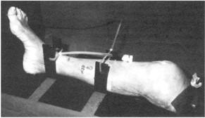
Figure I. Specimen mounted on a perspex plate with cod-liver oil markers in place
The specimen was then embalmed by vascular perfusion of the superficial femoral vessels within 60 hours of death using a solution containing: 50 g Phenol 99%, 20g MgS04 , 20 g NaS04 , 10 g NaCl, 60 ml formaldehyde 37%, 60 ml glycerine, H20 ad 1000 ml (Kleinrensink, 1995). After embalming, a second set of MR images was produced. Following the production of the second set of MR images, the specimen was cut with a handsaw into 2mm thick sagittal sl ices along the MRI scan plane. Subsequently the slices were dehydrated in 2 changes of cold acetone. After complete dehydration the slices were plastinated according the von Hagens E 12 technique described by von Hagens (von Hagens, I985; von Hagens, 1987; Weber and Henry, 1993). The exact position of the slices that are presented i n this study (mid-sagittal and lateral) is depicted on a three-dimensional CT model (G E pro-Speed scanner GE Medical Systems Milwaukee, Wis.USA) Slice thickness was 3 mm, pitch 1.0, 120KV, 100 mA and 2 second scan time.
Anatomical drawings were made by scanning the plastinated slices on a commercially available flatbed scanner followed by computerized elaboration using computer software (Coreldraw)
Magnetic Resonance Imaging
Contiguous MR images were produced with a slice thickness of millimetre along the plane defined by the markers i n the specimen, prior to and following embalming, with a Philips Gyroscan NT 1.0 Tesla (Philips Medical Systems, Best, the Netherlands). Four different sequences were used. These sequences were chosen either because of their ability to demonstrate anatomical detail or because they are commonly used in clinical practice. The sequences parameters were: 1. Spin echo technique, T1 weighted (TR 550, TE 16): anatomy; 2. Spin echo technique, T2 weighted (TR 1965, TE 80): pathology especially edema and effusions; 3. Spin echo technique, proton density (TR 1965, TE 15): pathology , especially menisci and ligaments and 4. Turbo spin echo technique, T2 weighted (TR 3750, TE 95, TSE factor 9): identical to technique 2 only with significantly shorter acquisition times (in this study, 3 versus 13 minutes).
Pre- and post-embalming MR images were compared with the plastinated slices. Overall signal intensity and tissue contrast was assessed, with special attention to anatomical structures such as cruciate ligaments, menisci, cartilage and the ability of MRI to distinguish these structures from the surrounding tissues before and after embalming.
In this study, the plastinated tissue slices were compared with the corresponding MR slices at 2 levels, mid-sagittal and lateral (Fig. 2).
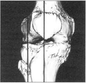
Figure 2. Three dimensional computed tomography image of the knee. The origin of the two slices is demarcated with a line.
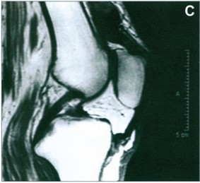
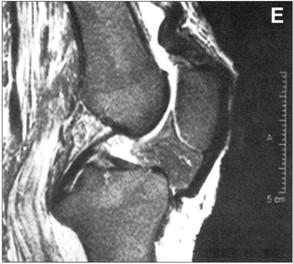
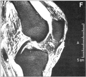
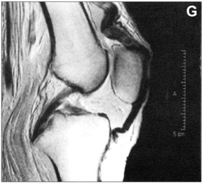
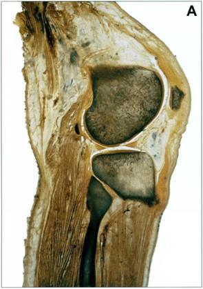
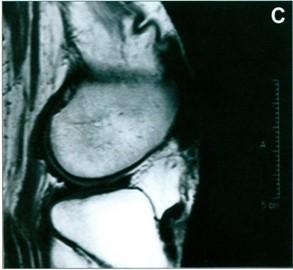
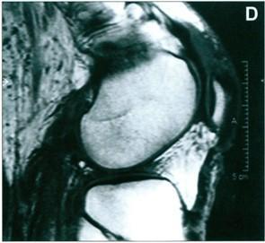
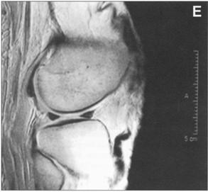
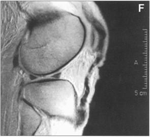
Figures 3 and 4 demonstrate the grossly visible structures located within these two regions : plastinated tissue slices (Figs. 3a, 4a) and MR images prior to and after embalming (Fig. 3c-h, 4c-f). The most striking effect was a significant swelling of the soft tissues that occurred due to the embalming technique. This caused some flexion of the knee, despite tight fixation on the perspex plate (Fig. 3c-h, 4c-f). Additionally , the amount of fluid in the suprapatellar recess of the knee joint increased leading to stretching of the tendon of insertion of the quadriceps muscle (Figs. 3e and f). While the diameter of the cruciate ligaments increased, however, their position and general shape remained unchanged . Moreover, signal intensity of the cruciate ligaments increased on Tl-weighted images and proton density images (Fig. 3c-d, g-h). The musculature around the knee showed significant swelling but differentiation between muscle and surrounding soft tissues was still possible (Fig. 4c-d). The menisci showed some increase in signal intensity on Tl -weighted and proton density images but otherwise its appearance did not change (Fig. 4c-f).
 |
 |
 |
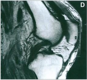 |
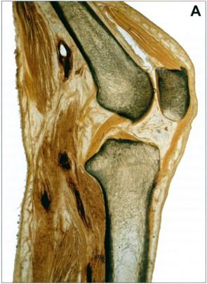
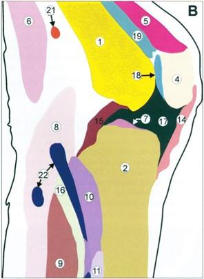
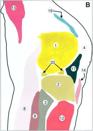
| Figure 3 a. Plastinated mid sagittal slice, b. anatomical drawing : 1. femur, 2 . tibia , 3 . fibula , 4 . patella , 5. tendon of m . quadriceps femoris, 6. M. semimembranous , 7. M. plantaris , 8. M. gastrocnemius (lateral head), 9. M. soleus, 10. M. popliteus, 11. Posterior tibial muscle, 12. Anterior tibial muscle, 13. Vastus lateral muscle, 14. Patellar ligament, 15. Posterior cruciate ligament , 16. Anterior cruciate ligament, 17. Infrapatellar fat body , 18. Suprapatellar bursa, 19. Adipose body , 20 . Lateral meniscus, 21 . Popliteal artery, 22 . Popliteal vein , c. T 1 weighted spin echo image prior to embalming, d. T 1 weighted spin echo images after embalming | |
As a result of embalming T2 weighted spin echo and T2 weighted turbo spin echo images showed a diffuse increase in signal intensity. T1 weighted spin echo images and proton density images showed a diffuse decrease in tissue contrast both resulting in a deterioration of image quality compared to the pre-embalming images. The image quality in all four techniques decreased due to a homogenization of signal intensity.
 |
 |
 |
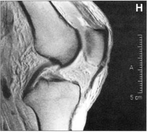 |
| Figure 3 e. T2 weighted spin echo image prior to embalming, f. T2 weighted spin echo image after embalming, g. proton density spin echo image prior to embalming, h. proton density spin echo image after embalming. | |
For this study we present three techniques which show either an increase, a decrease or no change in signal intensity (T2 weighted spin echo are not shown as they resemble T2 weighted turbo spin echo images). Figures 3 and 4, c through h, show MR images prior to and after embalming. For clarity line drawings are presented of the anatomical region according to a method we previously presented (Figs. 3b, 4b) (Entius, 1997).
 |
 |
 |
 |
 |
 |
| Figure 4 a. Plastinated lateral sagittal slice, b. anatomical drawing l . femur, 2 . tibia, 3 . fibula, 4 . patella , 5. tendon of m quadriceps femoris, 6. M. semimembranous , 7. M. plantaris, 8. M. gastrocnemius (lateral head) , 9. M. soleus, 10. M. popliteus, 11. Posterior tibial muscle , 12. Anterior tibial muscle , 13. Vastus lateral muscle , 14. Patellar ligament, 15. Posterior cruciate ligament, 16. Anterior cruciate ligament, 17. Infrapatellar fat body , 18. Suprapatellar bursa, 19. Adipose body , 20 . Lateral meniscus, 21 Popliteal artery, 22 . Popliteal vein, c. T 1 weighted spin echo image prior to embalming, T 1 weighted spin echo images after embalming e. proton density spin echo image prior to embalming, proton density spin echo image after embalming. | |
The embalming process deteriorated the quality of the MR images in four pulse sequences. However, for teaching purposes this degradation was not significant. Also correlation with plastinated slices was still possible. Our results suggest that embalmed material can be used in correlation studies and for educational purposes.
The difference in flexion of the knee before and after embalming was caused by diffuse swelling of the soft tissues around the knee joint, caused by the embalming process in which a large quantity of fixating fluid is administrated through the femoral artery. In our opinion this did not affect the comparison between pre- and post embalming images.
Although the degradation effect of the embalming process on the MR images does not significantly affect the interpretation of gross anatomical structures in the musculoskeletal system, further research is necessary to study the effect of embalming on microstructures and on other organ systems.
For educational purposes with regard to multi-planar visualization embalmed material can be imaged with MR imaging without significant loss of information compared to in vivo anatomy.
Acknowledgments: The authors wish to thank Teun Rijsdijk for his excellent assistance in preparing the photographs.
Baptista CAC, Henry RW, Williams G, Brinker R. 1990: Magnetic resonance imaging of plastinated specimens: Study of tissue characteristics and evaluation of the hardening process of the S10 technique. Abstract presented at The 5th International Conference on Plastination, Faculty of Medicine, University of Heidelberg, Germany July 1990. J Int Soc Plastination 4(1):3.
Cook P, Al-Ali S 1997: Submacroscopic interpretation of human sectional anatomy using plastinated E12 sections. J lnt Soc Plastination 12(2):17-27.
https://doi.org/10.56507/XICY2283
Entius CAC, van Rijn RR Holstege JC, Stoeckart R, Zwambom AW. 1997: Correlating sheet plastinated slices, computed tomography images and magnetic resonance images of the pelvic girdle: A teaching tool. Acta Anatomica 158:44-47.
https://doi.org/10.1159/000147909
Henry RW, Antinoff N, Janick L, Orosz S. 1997: El2 technique: An aid to study sinuses of psittacine birds. Acta Anatomica 158:54-58.
https://doi.org/10.1159/000147911
Hussain SM, Stoker J, Entius CAC, van Rijn RR, Zwambom AW, Hollander JC, Lamens JS. 1996: Endoanal magnetic resonance imaging of the anal sphincter complex with sheet plastined slices and histology . Eighth international conference on plastination. Brisbane, Australia, 5.
Kleinrensink GJ, Stoeckart R, Vleeming A, Snijders CJ, Mulder PGH, van Wingerden JP. 1995: Peripheral nerve tension due to joint motion; a comparison between embalmed and unembalmed human bodies . Clin Biomech 10(5):235-239 .
https://doi.org/10.1016/0268-0033(95)99800-H
Magiros M, Kekeic M, Doran GA. 1997: Learning relational anatomy by correlating thin plastinated sections and magnetic resonance images : Preparation of specimens. Acta Anatomica 158:37-43.
https://doi.org/10.1159/000147908
McNiesh LM, von Hagens G. 1988: The diagnostic imaging characteristics of plastinated anatomical specimens. J Int Soc Plastination 2(1):24-39.
https://doi.org/10.56507/RMEK8272
von Hagens G. 1985: Heidelberg Plastinationhefter; samrnlung aller Merlcblatter zur Plastination. D-6900 Heidelberg, Germany: Anatomisches Institut I. Universitat Heidelberg.
von Hagens G, Tiedemann K, Kriz W. 1987: The current potential of plastination. Anat Embryol 175(4):411-21.
https://doi.org/10.1007/BF00309677