1- Anatomia y Embriologia, Facultad de Veterinaria, Universidad de Murcia, Campus de Espinardo, 30071, Murcia, Spain.
2-Departamento de Morfologia, Facultad de Veterinaria, Universidad de Las Palmas de Gran Canada, Trasmontana, 35416, Arucas, Spain.
3-Department of Comparative Medicine, College of Veterinary Medicine, University of Tennessee, 2407 River Drive, Knoxville, TN, 37996, USA.
The efficacy of a combined use of P-40 and S10 Biodur™ techniques as an aid for radiographic anatomy is investigated. The purpose of this study was to use a combination of P-40 and S10 plastinated slices and magnetic resonance (MR) images to better understand the anatomy of the normal adult equine tarsus. Tarsi from four normal pure breed Spanish horses were utilized. The sagittal and transverse MR images were performed using a scanner with a 1.5 Tesla magnet. Macroscopic slices (2mm and 10mm in thickness) that correlated with the MR images were obtained from distal limbs whose synovial space (tarsocrural joint) and blood vessels were injected with colored latex. The results demonstrate that a combined use of semitransparent slices (P-40) and thick (S10) slices from the imaged specimens allows an accurate evaluation in MR images of many anatomic structures.
anatomy; equine; plastination; polymer; P-40; S10; tarsus
R. LATORRE: Telephone: 34 - 968 - 364 - 697; Fax: 34 - 968 - 364 - 147; E-mail: latorre@um.es

![]()


Imaging technologies such as magnetic resonance imaging (MRI), computed tomography (CT) and ultrasonography have created a need for in depth studies of sectional anatomy. Most of the combined anatomic and diagnostic explorations using MRI or CT used l cm thick macroscopic tissue sections which yielded good correlation of the tissue slices with the CT image (Denoix et al., 1993; Blaik et al., 2000; Vazquez et al., 2001). Classically these slices have been on fresh tissue that was later fixed. Unfortunately, body slices prepared by traditional formalin fixation methods are often unpleasant to handle and prone to deterioration. Various polymers such as silicone (Cooper et al., 1990; Weiglein, 1996), polymerizing emulsion (Margios et al., 1997), epoxy (von Hagens,1979; Entius et al., 1993; Weber and Henry, 1993) and polyester (Weiglein et al., 1997; Sora et al., 1999) have been used for producing anatomical slices to be compared with radiographic material. Each polymer yields different results. Silicone impregnated specimens are opaque, somewhat flexible and resilient. Polymerizing emulsion has been used for the plastination of extremity or body slices, but this process yields firm, opaque slices (Marigos et al., 1997). Epoxy resins are used for study of sectional anatomy with thin semitransparent body slices (2mm thickness) (von Hagens et al., 1987; Entius, 1993; Cook, 1997). The common epoxy technique for over two decades has been El2 sheet plastination. Polyester resin has been routinely used only for brain slices, resulting in excellent distinction between gray and white matter (von Hagens et al., 1987).
The aim of this work was to demonstrate that: 1. The P-40 technique can also be used to preserve semitransparent body slices, and 2. A combined use of these two plastination methods (S10 and P-40) can aid in a more accurate interpretation of MR images, than using only one technique.
Four Spanish pure breed horses were donated to the Large Animal Hospitals (Universities of Murcia and Las Palmas de Gran Canada. Spain). Their pelvic limbs were removed and used for this study and in conjunction with other research projects. These tarsi were scanned within 2 hours of euthanasia. At the conclusion of MR imaging, the arteries, veins and synovial spaces of the cleaned and shaved tarsi were injected with red, blue and green latex, respectively. To produce these colors, white latex was colored using pigment paste (2% ppv): AC50 (red), AC52 (blue) and AC54 (green) (Biodur™, Heidelberg). The femoral artery was used for arterial injection. Injection was concluded when latex oozed from the smaller cut arteries. Then one of the two plantar digital veins was used, as distal as possible, to inject the venous system. Proximally the veins were ligated when blue latex reached the open end. The plantar pouches (lateroplantar and medioplantar) were utilized for injection of the tarsocrural joint space. Sagittal and transverse slices were then prepared to demonstrate the anatomic relationships of structures of the tarsus.
MR Images
A Genesis-Sigma scanner (General Electric Medical Systems from Special Diagnostic Service of San Roque Clinic, Ayalon, Las Palmas de Gran Canaria, Spain) was used to produce MR images. The unit had a superconducting magnet operating at a field of 1.5 Tesla. To obtain the images, the specimens were placed, with the tarsal and digital joints in extension, within a human extremity coil. Images were acquired using a spin echo pulse sequence. Sagittal and transverse images were acquired in proton density (PD) weighted with the parameters show in table 1.
| Sagittal | Transverse | |
| Repetition time | 3160 msec | 3160 msec |
| Echo | 14 msec | 15 msec |
| Echo number | 1 | 1 |
| Number of excitations | 1 | 1.5 |
| Matrix size | 512 X 224 | 512 X 224 |
| Slice thickness | 6 mm | 6 mm |
| Spatial resolution | 11 mm | 11 mm |
Two hundred and thirty MR images were taken at the various tarsal joint levels (transverse and sagittal). Images that had the best correlation with the sagittal and transverse macroscopic slices were selected.
Slicing
After latex injection, the limbs were frozen at -80°C. After freezing, transverse and sagittal slices were made from the distal tibia to the proximal metatarsus on a high-speed band saw at desired thicknesses (2mm and 10mm). Liquid nitrogen was used to cool the saw table for production of the 2mm slices. The following slicing pattern (10mm/2mm/2mm/10mm/2mrn/2rnm/10mm) was used. Slices were placed on grids. Saw dust was removed by submerging tissue slices in cold acetone and scraping, or flowing a small stream of cool tap water quickly across the slice. A minimum of twenty slices were made from each tarsus. Both surfaces of each slice were photographed prior to fixation. Standard P-40 and S10 techniques (von Hagens, 1985; von Hagens et al., 1987; Henry and Nel 1993) respectively were used to plastinate the 2 and 10mm slices.
Fixation
Only the 10mm thick slices were fixed. These slices were submerged in a 10% formaldehyde solution for 15 days at cool temperature (2°C). After removal from the fixative, they were washed under running tap water for one day.
Dehydration
The slices were dehydrated in cold acetone (freeze substitution). Cleaned slices on their grids were submerged in vats containing 10X the specimen volume of 90% acetone at -20°C. Two changes of 100% cold acetone were carried out at weekly intervals.
Forced Impregnation
After dehydration, the slices were separated into two groups. Group 1 consisted of the 10mm thick tissue slices which were plastinated according to the standard cold S10 technique (Biodur™). Group 2 consisted of all the 2mm thick tissue slices which were plastinated at room temperature using the P-40 technique (Biodur™).
Reaction mixtures
Group 1: Polymer SR10 + Catalyst SH03 (1% ppv) (Biodur™, standard silicone procedure, at - 20°C) (von Hagens, 1985).
Group 2: Polymer P-40 (BiodurTM, room temperature polyester procedure) was used in a darkened chamber.
Tissue slices were immersed in the reaction mixtures and placed into a vacuum chambers. Pressure was gradually decreased for both groups until a pressure of <5mm Hg (group 1) and 10mm Hg (group 2) was attained. These pressures were maintained until bubbling ceased.
Curing
Group 1: The slices were removed from the polymer reaction mixture. Excess polymer was drained and wiped from the slices. The silicone impregnated slices were placed in an airtight container with S6 crosslinker (SH06 Biodur™) (von Hagens, 1985). The S6 was vaporized ten minutes daily using an aquarium pump. The slices remained in this environment one week. During this period the slices were turned and wiped of excess polymer three to four times a day. Finally, the slices were placed in a plastic bag containing vaporized S6 for 2 months allowing complete curing of the slices.
Group 2: Each impregnated slice was removed from the impregnation bath and placed into casting chambers fashioned from two sheets of 3mm tempered glass, a silicone gasket and fold back clamps (Weber and Henry, 1993). The chambers were filled with fresh P- 40, closed and sealed with . The slices were exposed for four hours to ultraviolet-A lights. The UV-A light was alternately turned on for 15 minutes intervals and off for 30 minutes to avoid excess heat build up during this curing phase. During curing, a ventilator was used to cool the chambers. When the curing was completed, the glass chambers were dismantled and the slices trimmed.
In this study, the plastination of tissue slices of the tarsus was a valuable tool for interpretation of tarsal MR images. Each slice and MR image provided detailed information on the anatomy for the equine tarsus. Both sagittal and transverse MR images, as well as, plastinated slices yielded remarkable detail (Figs,1a, 2a, 3a,4a). In fresh macroscopic slices (Figs, 1b, 2b, 3b, 4b), S10 plastinated slices (Figs, 1c, 2c, 3c, 4c) and P- 40 plastinated slices (Figs. 1d, 2d, 3d, 4d) distinction of individual structures and their anatomic relationships were easily noted and remarkably useful when viewing and comparing to one another.
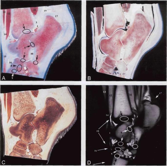 Figure 1. Sagittal sections of the equine tarsus: Fresh macroscopic section (A), S10 plastinated section (B), P-40 plastinated section (C), MR image (D). 1. Labium mediale trochlea tali, 2. Articulatio tarsocruralis, 3. Capsula articularis, 4. Recessus lateroplantaris (articulatio tarsocruralis), 5. Articulatio talocalcanea, 6. Articulatio calcaneocuartalis, 7. Articulatio talocalcaneocentralis, 8. Articulatio centrodistalis, 9. Articulatio tarsometatarseae, 10. Sinus tarsi, 11. M. flexor digitorum profundus, 12. M. tibialis cranialis, 13. M. extensor digitorum longus, 14. M. peroneus tertius, 15. M. extensor digitorum longus (tendo), 16. M. tibialis cranialis (tendo cranialis), 17. M. flexor digitorum superficialis (tendo), 18. Vagina tendinis (m. tibialis cranialis), 19. Bursa calcanea (m. flexoris digitorum superficialis). |
Sagittal sections (Figs. 1, 2) in general yield a clear differentiation between the tarsocrural, intertarsal (talocalcaneal, calcaneoquartalis, talocalcaneocentralis, centrodistalis), and tarsometatarsal joints. The semi- transparent plastinated macroscopic slices (P-40) accurately show the different ligaments (tibiocalcaneal, talocentrodistometatarsal, long plantar, tibiotalar) and other structures such as the tarsal sinus and tarsal canal. While S10 sections exhibit an excellent contrast between adipose tissue, which appears white, other tissues such as the lateral and medial plantar nerves and muscle bundles were also easily identified.
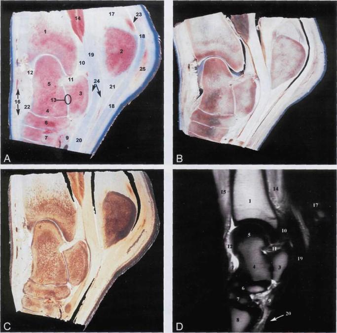 Figure 2. Medial parasagittal sections of the equine tarsus: Fresh macroscopic section (A), S10 plastinated section (B), P-40 plastinated section (C), MR image (D). 1. Tibia, 2. Tuber calcanei, 3. Sustentaculum tali, 4. Corpus tali, 5. Trochlea tali, 6. Os tarsi centralis, 7. Os tarsale III, 8. Os metatarsal III, 9. Os tarsale I + II, 10. Capsula articularis, 11. Ligamentum tibiocalcaneo plantaris, 12. Recessus dorsomedialis (articulatio tarsocruralis), 13. Articulatio talocalcanea, 14. M. flexor digitorum profundus, 15. M. tibialis cranialis, 16. M. tibialis cranialis (tendo medialis/cuneans), 17. Tendo calcaneus communis, 18. M. flexor digitorum supfercialis (tendo), 19. M. flexor digitorum lateralis (tendo), 20. M. flexor digitorum profundus (tendo), 21. Ligamentum plantare longum, 22. Ligamentum talocentrodistometatarseum, 23. Bursa calcanea m. flexoris digitorum superficialis, 24. Vagina tendinis m. flexor digitorum lateralis, 25. Bursa subcutanea calcanea. |
Transverse sections compliment MR images (Figs. 3, 4), and tarsal structures like tendons, intertarsal joints and synovial pouches could be identified. Plastinated transverse sections yielded much information about the extent of joint capsule and the relationship with collateral ligaments and bones (talus and calcaneus). Transverse S10 plastinated slices (Fig. 3c) displayed a superb differentiation of the dorsomedial, lateroplantar and medioplantar synovial pouches, and the medial (Cunean) tendon of tibialis cranialis. These structures were not as distinct in the MRI and P-40 plastinated slices. However, transverse plastinated P-40 sections (Fig. 3d) showed a clear differentiation between the tibialis cranialis, peroneus tertius and long digital extensor muscles. These muscles were more difficult to differentiate in the MR images and S10 plastinated slices. The relationships of the lateral digital extensor and medial digital flexor tendons and their relation with the collateral ligaments were easily analyzed in the P-40 transverse sections. However, these relationships were more difficult to discern in MR images and S10 plastinated slices.
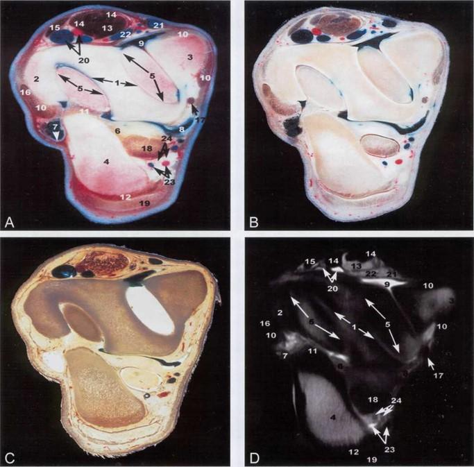 Figure 3. Transverse sections of equine tarsocrural joint: Fresh macroscopic section (A), S10 plastinated section (B), P-40 plastinated section (C), MR image (D). 1. Tibia (cochlea), cartilago articularis (arrow), 2. Malleolus lateralis, 3. Malleolus medialis, 4. Tuber calcanei, 5. Trochlea tali (labiae), cartilago articularis (arrow), 6. Capsula articularis, 7. Recessus lateroplantaris (articulatio tarsocruralis) (arrow), 8. Recessus medioplantaris (articulatio tarsocruralis), 9. Recesus dorsomedialis (articulatio tarsocruralis), 10. Ligamenta collateralia lateral et medial, 11. Ligamentum talocalcaneum laterale, |
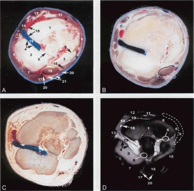 Figure 4. Transverse sections of equine limb at the level of the central tarsal bone: Fresh macroscopic section (A), S10plastinated section (B), P-40 plastinated section (C), MR image (D). 1. Os tarsi centralis, 2. Os tarsale IV, 3. Os tarsale I+II, 4. Canalis tarsi, 5. Articulatio centrodistalis, 6. Ligamenta collateralia tarsi laterale et mediale longum, 7. Ligamentum plantare longum, 8. Ligamentum talocentrodistometatarseum, 9. M. tibialis cranialis (tendo medialis/cuneans), 10. M. tibialis cranialis (tendo cranealis), 11. M. peroneus tertius (tendo cranealis), 12. M. extensor digitorum longus (tendo), surrounded by its vagina tendinis, 13. M. extensor digitorum lateralis (tendo), 14. M. extensor digitorum brevis, 15. M. flexor digitorum medialis (tendo), 16. M. flexor digitorum lateralis (tendo) et m. tibialis caudalis (tendo), 17. M. flexor digitorum superficialis (tendo), |
The tarsal joint is an anatomically complex area and an understanding of this is a prerequisite for accurate diagnosis of injuries in this joint. The results of this work show that the combined use of semitransparent (P-40) and thick (S10) slices from the same specimen each offer detailed information which can be an aid for interpretation of MR images.
Our results demonstrated that images from fresh macroscopic slices, before they were plastinated, were also useful to determinate some anatomical structures. This was especially such when comparing these images with the plastinated slices. We could not find any author who reported using recorded images prior to plastination to interpret the plastinated specimen.
The quality of S10 and P-40 plastinated and fresh slices was excellent. Many structures (vessels, synovial membrane or synovial sheaths) were more readily identifiable when the plastinated slices were compared
with their own fresh images. The shrinkage of surrounding connective tissue in S10 sections permits better identification of nerves. The better optical properties of some anatomic structures as ligaments and tendons in the P40 sections makes identification easier.
S10 plastinated sections provided confirmation that the MR images obtained were a true representation of that area of the body, which is consistent with previous reports (Cooper et al., 1990; Weiglein, 1996, Marigos et al., 1997). The direct comparison between sheet serial sections (P-40) and the equivalent MR images provided a clearer understanding of anatomical structures. This should enhance clinical interpretation and is similar to reports for E-12 sheet slices (Entius et al., 1993). The classic epoxy (E-12, Biodur™) method has been used for over two decades to produce routine slices in veterinary anatomy (Weber and Henry, 1993) or human anatomy (Entius et al., 1993; Cook, 1997). But epoxy often yellows within a few days or weeks after casting and when impregnation is complete there is only a short window of time in which to cast the slices (von Hagens, 1985). In this sense, several authors have worked to improve these limits (Latorre et al., 2002a, b; Reed et al., 2002). However, the results of P-40 sections in this study did not have these limitations. Our results with P40 were similar to those previously reported using polyester (P-35 or P-40) to preserve sheet body slices (de Boer-van Huizen et al., 1993; Latorre et al., 2002c; Weiglein et al., 2002).
The findings of this study indicate that the P-40 method (Biodur™) could be used to produce body sections for comparison with MR images. A combined use of transparent (P-40) and thick (S10) slices from the same specimen allowed an accurate evaluation of many anatomic structures in the MR images.
Acknowledgements: This work was supported by Seneca Foundation, Comunidad Autonoma de la Region de Murcia (project number: PC/2/FS/99). The authors wish to thank Mr. Mariano Orenes and Ms. Helena Abell&n of Murcia University for their excellent technical expertise in preparing the material; personal from Special Diagnostic Service of San Roque Clinic, Ayalon, Las Palmas de Gran Canaria, Spain, for their technological skills, time and patience throughout the MR scanning process.
Blaik MA, Hanson RR, Kincaid SA, Hatchcok JT, Hudson J A, Baird D K. 2000: Low-Field magnetic resonance imaging of the equine tarsus: normal anatomy. Vet Radiol & Ultrasound 41:131-141.
https://doi.org/10.1111/j.1740-8261.2000.tb01466.x
Cook P. 1997: Sheet plastination as a clinically based teaching aid at the University of Auckland. Acta Anat 158:33-36.
https://doi.org/10.1159/000147907
Cooper M. 1990: The technique and use of plastinated specimens in teaching and research: Gross anatomical sections of the head and neck. Abstract presented at The 5th International Conference on Plastination, Faculty of Medicine, University of Heidelberg, Germany July 1990. J Int Soc Plastination 4(1):4.
de Boer-van Huizen, RT, Cornelissen CJ, ten Donkelaar HJ. 1993: The P35 technique for sheet plastination of the human head. Abstract presented at The 6th International Conference on Plastination -Kingston, Ontario, Canada - July 1992 J Int Soc Plastination 7:36.
Denoix J M , Crevier N , Roger B, Lebas J F. 1993: Magnetic resonance imaging of the equine foot. Vet Radiol & Ultrasound 34:405-411.
https://doi.org/10.1111/j.1740-8261.1993.tb02029.x
Entius CAC, Kuiper JW, Koops W, de Gast A. 1993: A new positioning technique for comparing sectional anatomy of the shoulder with sectional diagnostic modalities: Magnetic Resonance Imaging (MRI), Computed Tomography (CT) and Ultrasound (US). J Int Plastination 7:23-26.
https://doi.org/10.56507/MIIH4716
Henry RW, Nel PPC. 1993: Forced impregnation for the standard S10 method. J Int Soc Plastination 7:27- 31.
https://doi.org/10.56507/WUXP9436
Latorre RM, Reed RB, Gil F, Lopez-Albors O, Ayala MD, Martinez-Gomariz F, Henry RW. 2002: Epoxy impregnation without hardener: to decrease yellowing, to delay casting and to aid bubble removal. J Int Soc Plastination 17:17-22.
https://doi.org/10.56507/LZKY8224
Latorre R, Vazquez JM, Gil F, Ramirez G, Lopez- Albors O, Ayala M, Arencibia A. 2002b: Anatomy of the equine tarsus: A study by MRI and macroscopic plastinated sections (S10 and P40). Abstract presented at The 11th International Conference on Plastination, San Juan, Puerto Rico, July 14-19, 2002. J Int Soc Plastination 17:6-7.
Latorre RM, Reed RB, Henry RW. 2002c: Epoxy impregnation with no hardener. Abstract presented at The 11th International Conference on Plastination, San Juan, Puerto Rico, July 14-19, 2002. J Int Soc Plastination 17:7.
Margios M, Kekic M, Doranet GA. 1997: Learning relational anatomy by correlating thin plastinated sections and magnetic resonance images: Preparation of specimens. Acta Anat 158:37-43.
https://doi.org/10.1159/000147908
Reed RB, Henry RW. 2002: Epoxy under vacuum. Abstract presented at The 11th International Conference on Plastination, San Juan, Puerto Rico, July 14-19, 2002. J Int Soc Plastination 17:8.
Sora MC, Brugger P, Traxler H. 1999: P40 plastination of human brain slices: Comparison between different immersion and impregnation conditions. J Int Soc Plastination 14(l):22-24.
https://doi.org/10.56507/XLSJ5724
Vazquez, JM, Rivero M, Gil F, Ramirez JA, Ramirez G, Vilar JM, Arencibia A. 2001: Magnetic resonance imaging of two normal equine brains and their associated structures. Vet Rec 148:229-232.
https://doi.org/10.1136/vr.148.8.229
von Hagens, G. 1979: Impregnation of soft biological specimens with thermosetting resins and elastomers. Anat Rec 194(2):247-255.
https://doi.org/10.1002/ar.1091940206
von Hagens G. 1985: Heidelberg Plastination Folder: Collection of all technical leaflets for plastination. Heidelberg, Germany: Anatomisches Institut 1,Universitat Heidelberg
von Hagens G, Tiedemann K, Kriz W. 1987: The current potential of plastination. Anat Embryol 175(4):411-421.
https://doi.org/10.1007/BF00309677
Weber W, Henry R W. 1993: Sheet plastination of body slices-El2 technique, filling method. J Int Soc Plastination 7:16-22.
https://doi.org/10.56507/EZGX2343
Weiglein AH, Henry RW.1993: Curing (hardening, polymerization) of the polymer - Biodur S10. J Int Soc Plastination 7:32-35.
https://doi.org/10.56507/ABNZ7085
Weiglein AH. 1996: Preparing and using S10 and P-35 brain slices. J Int Soc Plastination 10:22-25.
https://doi.org/10.56507/IXGV4189
Weiglein AH, Bahadori K, Feigl G. 1997: Congruent CT-scans and plastinated slices. Abstract Presented at The 5th Interim Meeting on Plastination University of Tennessee, Knoxville, TN, USA. June/July 1997. J Int Soc Plastination 12(2):35.
Weiglein AH, Kqiku L, Pertl C. 2002: Inferior alveolar nerve anatomy revisited: A study based on dissection and plastination. Abstract presented at The 11th International Conference on Plastination, San Juan, Puerto Rico, July 14-19, 2002. J Int Soc Plastination 17:10.