1- Anatomia y Embryologia, Facultad de Veterinaria, Universidad de Murcia, Murcia, Espafzia, Europe.
2- Department of Comparative Medicine, College of Veterinary Medicine, University of Tennessee, 2407 River Drive, Knoxville, TN, 37996-4543, USA.
Plastination has developed into the gold standard for preservation of biological tissues and specimens. Plastination has been applied to many areas: anatomy, art, biology, clinical medicine, surgery and research . Semi-transparent 2-3mm body slices which display sectional anatomy in conjunction with its anatomical surroundings are produced using the P40 polyester technique . These manufactured slices are excellent aids for teaching medicine and to help understand modem diagnostic images: Computed tomography, Magnetic resonance and Ultra sound. Originally the polyester technique was developed for presentation of brain tissue. However in this decade, polyester is being used with a variety of tissues .
plastination; polyester method; body slices; polyester resin; P40; A4
R. Latorre- Anatomia y Embryologia, Facultad de Veterinaria, Universidad de Murcia, Murcia, Espafzia, Europe. Telephone: (34) 986 364 697; Fax: (34) 986 364 147; E-mail: latorre@um.es

![]()


Polyester impregnated slices of biological tissue, manufactured in glass-flat chambers, are a useful format for anatomical study or research (Barnett, 1997; Henry and Weiglein, 1999; Sora et al., 1999; Weiglein and Feigl, 2001; Latorre et al., 2002). Classically, 4-8mm slices of nervous tissue were the norm (von Hagens, 1990). The P35 resin was developed in the late 1980's and remains the gold standard for brain slice production. In the mid 1990's, the P40 resin was introduced as a less complex technique. Currently, thinner slices are prepared with P40 (von Hagens, 1994). However, their white/gray differentiation is second alone to the exquisite differentiation of white and gray matter of brain slices of the P35 process.
Polyester plastination utilizes the same basic principals of the classic silicone plastination techniques (von Hagens, 1979a; 1979b; 1986; von Hagens et al., 1987; Henry and Nel, 1993). Tissue fluid is removed and is replaced with a curable polyester resin. More recently, P40 polyester resin is used also for body slices (Latorre et al., 2002; 2004). P35 has been used to prepare head slices (de Boer-van et al., 1993). P40 also was used to plastinate a nerve plexus (Sora, 1998). P45 resin is a new comer to the polyester methodology (Gao et al., 2006) and uses heat as its catalyst. These resins utilize similar methodology with impregnation and casting between glass plates their unique features. Dual manuscripts present the production of P40 body slices as well as the production of P40 brain slices.
Chemicals used in polyester-plastination include:
The BiodurTM products for polyester plastination are: P40: Epoxy resin
A4: Activator
The basic steps of plastination are: specimen preparation, dehydration, impregnation and curing.
Specimen preparation
Note for production of P40 body slices, the steps of specimen preparation, slicing and dehydration are the same as for the E12 epoxy technique. Please refer to this section of "E12 epoxy technique" for more details.
Specimen preparation equipment:
Specimen preparation - body slices:
The .selected specimen is positioned for proper anatomical alignment and frozen preferably in an ultra cold. deep freezer for two days (longer for larger specimens). Fresh tissue is preferred. Tissue should be fed in formalin if deemed a potential for exposure to b10hazards that may be associated with routine handling and sawing of biological tissues (Smith and Holladay , 2001). Preservation of tissue color is the best reason not to use formalin. Specimens covered with hair should have heir hair clipped. Ultra-cold freezing is necessary to yield the best tissue slices. Formalin fixative solutions containing other chemical additives should be thoroughly rinsed to deplete the tissue of any chemicals that potentially may react adversely with the resin.
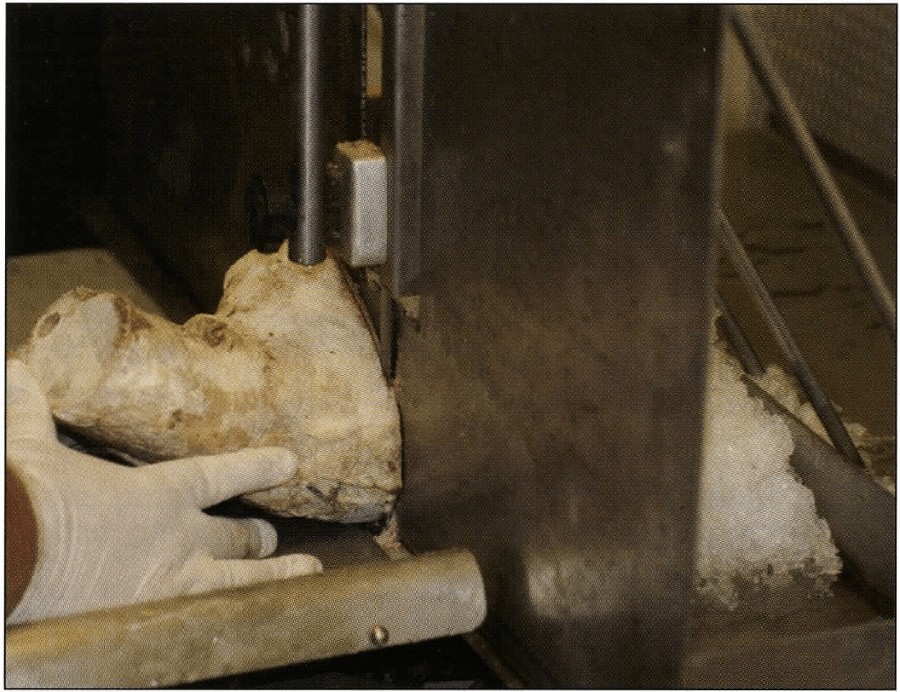
Figure 1. Slicing frozen tissue block on a band saw.
Slicing: The slices of the frozen specimen are cut on a bad saw (Fig. 1). A guide stop is necessary for cutting uniform sections. Cooling the stop and/or saw table with ice prevents premature thawing of the specimen, as well as the slices. The proposed plane of section of the specimen is determined and the end of the tissue block is squared for commencing sawing. Whole cadavers or large specimens should be cut into smaller more manageable portions. This not only facilitates handling of the specimen but also prevents excessive thawing of the remaining specimen while sawing is taking place. The guide stop is set for the desired specimen thickness (2-3mm) and serial sections are sawed. As slices are produced , they are placed on metal or plastic grids (acetone resistant) in preparation for saw dust removal (Fig. 2). Dust removal may be done by: Returning the slice on the grid into the freezer and scraping the dust with the knife blade in the cold environment· Submerging the frozen slice in the first dehydration bath and scraping the dust from the specimen while submerged; or Running a rapid, small stream of tap water across the surface of the slice while scraping the surface with a knife (Fig. 3). Caution should be used and not allow the slice to thaw, especially unfixed brain tissue. The grids with their cleaned slices are stacked in the cold acetone (-25°C) of the first acetone bath (Fig. 4). Slices must be submerged to prevent drying/freezer burn of the slices. The stacked grids with their slices should be tied together in a bundle (Fig. 5) or placed into a basket for convenience and ease of transfer from on acetone bath to another and into the impregnation resin.
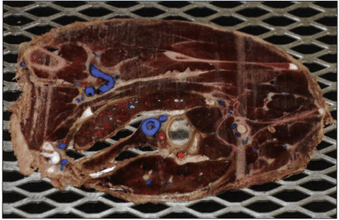 Figure 2. Saw dust covered slice on grid. |
 Figure 3. Slice after saw dust removal. |
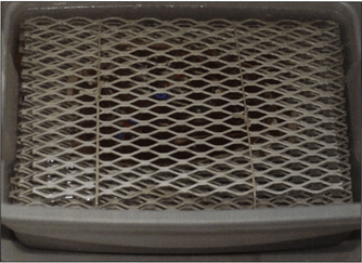 Figure 4. Bundled slices in first acetone bath. |
 Figure 5. Bundled slices |
Dehydration and degreasing of body slices
The recommended dehydration procedure for plastination is freeze substitution in -25°C acetone.
Dehydration equipment:
Shrinkage is minimal when cold acetone is used. For all plastination techniques, acetone is the ideal dehydrant and serves both as the dehydration and defatting agent, as well as the intermediary solvent. Also, acetone readily mixes with the resins used for plastination. The bundle of slices is submerged in the first cold acetone bath which may be less than 100% (>90%) purity. The slices should be tilted a few degrees as they enter the acetone bath and agitated after submersion to remove trapped air bubbles . Trapped air bubbles can cause drying of tissue which can show up on the finished slice. After the slices have been in the fist cold acetone bath for 3 days, the stack of body slices in the basket or bundle is removed briefly from the first acetone bath. The excess acetone is allowed to drip off quickly to prevent surface drying. Then the slices are submerged in the second cold (-25°C) 100% acetone bath. Caution: Dehydrated slices, especially brain, become brittle and break easy - Handle with CARE! After two or three days in the second bath the purity of acetone is checked with an acetonometer .'The acetone bath must be stirred and the acetone temperature must match the temperature calibration of the acetonometer (+ l5°C, +20°C or -10°C). Therefore acetone must be warmed or cooled to match the calibrated temperature before measuring and recording the purity If the acetone concentration is more than 98%, dehydration is considered complete. However if more than 2% water remains (<98% acetone purity), a third dehydration bath must be used to complete dehydration. Degreasing of body slices is essential to obtain the best resolution of adjoining tissues. Degreasmg should not be done on brain slices, degreasing will cause excess shrinkage of the slices.
Degreasing of body slices
Degreasing of body slices is accomplished by setting the dehydrated body slices out of the deep freezer into room temperature for the necessary time for degreasing to occur (1 - 3 weeks). Monitor degree of degreasing by observing fat color and acetone color. Acetone will tum yellow as the fat is leached. The acetone should be changed to a fresh bath when the yellow color has become intense. Fat will change from its white color to opaque when defatting is nearing completion. If more transparency of fat is desired, dehydrated slices may be placed into methylene chloride (dichloromethane) (MeCl) for one or two days. Monitor degreasing in MeCl daily. When body slices are appropriately degreased, transfer the slices from their bath (acetone or MeCl) into the impregnation resin.
Impregnation equipment:
Preparing impregnation-mixture: The polyester impregnation bath can be P40 resin with no additives or a Combination of P40 resin plus 1-2% A4 (activator).
Immersion into P40 resin of body slices: The dehydrated and degreased body slices are transferred into and submerged in a room temperature impregnation bath which must be kept darkened since light serves as the catalyst for this polyester. This impregnation bath can consist of P40 resin alone or may be a combination of P40 resin plus 1-2% A4 (activator). The slices in the resin can be placed in the vacuum chamber and vacuum can be applied and impregnation started immediately. However, it is beneficial to allow the slices to sit in the P40 resin overnight and equilibrate before applying vacuum and commencing forced impregnation. It is necessary to keep the vacuum chamber covered from light. The polyester resin is activated by light. Impregnation may be carried out at room temperature or in the cold (+5°C).
Forced Impregnation of body slices: The vacuum pump is turned on the next morning and allowed to warm to working temperature . Once the pump has warmed, vacuum is applied. The vacuum chamber must be kept darkened. Frequent regulation of the rate of evacuation (lowering pressure) is necessary especially in the beginning to evacuate the air trapped in the resin . As the pressure is lowered, air will boil from the resin and be pumped off. When pressure is lowered to the vapor pressure of the solvent (Acetone 22cm/9in Hg, MeCl 43cm/17in Hg @ +25°C), solvent will begin to vaporize (Henry, 2005a; 2005b). It will exit from the slices leaving a tissue void into which the polyester resin enters. The volatilized solvent is pumped out through the exhaust of the pump. The goal should be to keep the impregnation rate at a moderate boil and pressure slowly decreasing over the rest of the day and night. Resin level must be monitored and more P40 added if the level drops and exposes the top slices. The pressure level by the end of the day should be around 5cm Hg for room temperature or 2cm Hg for cold room impregnation. The pump is allowed to pump over night. The next day pressure is decreased incrementally to lcm Hg at room temperature or l-2mm Hg in cold temperature over the conclusion of this 30 hour impregnation period. Monitor the rate of decrease by bubble production, keep a moderate boil. When these pressure levels are reached and maintained for a few hours, impregnation is complete. Because the resin contains styrene which is released at low pressure, the lower limits of pressure are suggested to prevent styrene release from the resin and damaging the vacuum pump (von Hagens et al., 1987). When bubble formation decreases considerably, impregnation is nearly complete, however bubbling may not completely stop.
After impregnation is complete, the chamber is returned to atmospheric pressure . The box containing the slices and the P40 impregnation bath is removed and kept in a dark environment.
Curing or hardening the resin
UVA light serves as the catalyst for this polyester resin. The impregnated slices are places between two glass plates to obtain smooth surfaces of the specimen.
Curing equipment:
Preparing Glass/ Casting Chambers for brain slices: Two methodologies for constructing casting chambers are used: a. Building the chamber around a slice; b. Building the chamber for later insertion of a body slice into the chamber. Insertion of the body slice after construction is recommended only for slices that do not have multiple parts. Each casting (flat) chamber is prepared from two same and appropriate sized pieces of window (2mm or l/16in) glass, silicone gasket and large fold-back (folder) clamps. The gasket length should be similar to the length of the perimeter of the glass. Both top and bottom sides of the chamber consist of one sheet of window (float) glass. To prepare to accept a slice, one glass plate will be placed on an assembly stand (block of Styrofoam or box) and construction begun as follows:
a. Building flat chamber around a body slice: An individual slice on its grid is removed from the resin and excess resin allowed to drain briefly before placing the slice onto the center of the glass which is setting on the assembly A silicone gasket (4mm for a 2mm slice) is placed on the glass, 2cm from the bottom edge (Fig. 6). The gasket length is divided 2/3 to 1/3 from the center point of the glass. This will allow enough length to pass across the top of the glass and close the top of the flat chamber. Later the ends of the gasket will continue up the sides lying 2cm from the edge in preparation to seal the casting chamber. A spacer is placed near the top of the glass which will support the top edge of the top glass. Next the top glass plate is placed on top of the slice, spacer and gasket (Fig. 7). Fold-back clamps are placed along the perimeter of the bottom glass over laying the gasket. Care is taken to align the clamping edge of the fold-back clamp over the gasket which will assure the best seal possible. Both ends of the gasket are turned (90° angle) toward the top and positioned 2cm from the edge of the glass. Clamps are positioned directly over the gasket as before. The top remains open with the excess gasket hanging from each side. The clamps secure and seal the glass plates with the gasket. Next, fold the bottom clamp handles onto the glass and stand the flat/glass chamber, containing the body slice, vertically with the open top directed upward. The flat (casting) chamber, containing the specimen, is filled with the fresh well-mixed P40 resin or P40/A4 (100:1-2) mixture. A flat funnel is used to fill the chamber with P40 (Fig. 8). Air bubbles are poured with the resin into the chamber and must be allowed to rise to the surface. Some bubbles will catch on the surface of the slice and must be encouraged to rise. A small wooden wedge inserted in the opened top will spread the glass and aid bubble removal. A 1 mm wire may be used to tease or encourage a bubble to float to the surface. Leaning the chamber from side to side will encourage trapped bubbles to rise. Check both sides for bubbles. Use the wire to center the slice in the chamber. Close the top of the chamber with the remaining longer length of the gasket and fold back clamps. Make sure the resin level totally fills the chamber. Remove any air bubbles lying against the top gasket (Fig. 9). Air interferes with the curing of the P40 resin. Seal the junction of the bent ends of the gasket with a 4mm ball of Biodur gasket seal (HS 80). Inspect for large air bubbles trapped along the upper gasket. Remove bubbles by insertion of an I8ga (1.2mm) hypodermic needle between the glass and the gasket.
b. Build chamber for later insertion of a body slice: Position a glass on the assembly An appropriate size and length silicone gasket is placed 2cm from the bottom edge and its length is divided 2/3 to 1/3 at the midpoint of the glass. The longer end will be used to close the top space after filling. Later the ends of the gasket will continue up the sides lying 2cm from the edge in preparation to seal the casting chamber. A spacer placed near the top of the glass will support the top glass. The top plate is placed on top of the spacer and gasket. Fold-back clamps are placed along the perimeter of the bottom of the glasses over-lying the gasket. Align the clamping edge over the gasket to assure the best seal possible. Both ends of the gasket are turned (90° angle) toward the top and positioned 2cm from the edge of the glass. Clamps are positioned directly over the gasket. The top remains open with the excess gasket hanging to each side. The positioned clamps now secure and seal the glass plates with the gasket along the bottom and the sides. Next, fold the bottom clamp handles onto the glass and stand the flat/glass chamber vertically with the open top directed upward. A body slice is inserted through the top opening and the flat (casting) chamber now containing the specimen is filled with the fresh well-mixed P40 resin or the P40/A4 (100:1-2) mix (Fig. 8). Allow air bubbles to rise to the surface. Trapped bubbles need to be encouraged to rise to the top by using a small wooden wedge in the opened top and a 1 mm wire along with leaning the chamber from side to side. Close the top with the remaining longer length of the gasket and fold back clamps making sure to release any bubbles trapped against the top gasket (Fig. 9). Seal the junction of the bent ends of the gasket with a 4mm ball of Biodur gasket seal (HS 80). Inspect for large air bubbles trapped along the upper gasket. Remove bubble by insertion of an I8ga (1.2mm) hypodermic needle or 1 mm wire between the glass and the gasket.
Tip I: Insert one or two 3mm ball bearings into the chamber before closing the top. They can be used to centrally position and align the slice to your specification with the aid of a heavy duty magnet. This is also helpful if the slice moves while you transport and position it between the UVA lights.
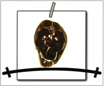 Figure 6. Building the casting-chamber around the slice: 2mm glass, slice, spacer and gasket. |
 Figure 7. Building chamber: Positioning top glass. |
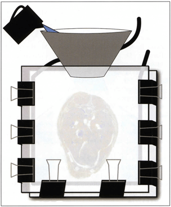 Figure 8. Bottom of fold back clamps turned onto glass. Flat funnel is used to fill chamber with P40 resin. |
 Figure 9. Closing top gasket and air bubble removal. |
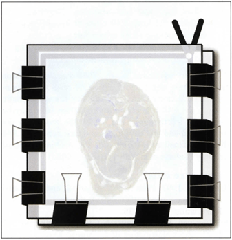 Figure 10. Sealed flat chamber ready for horizontal positioning and UVA light curing as the catalyst. |
Light Curing: After casting, to initiate and finalize curing, the sealed glass chambers filled with resin and a slice (Fig. 10) are exposed to UVA-light. A minimum of one hour is recommended for curing, depending on the wattage and distance of the UVA lamps. Typically four - 40 watt UVA light bulbs (tubes) are used. Two are placed above and two below the glass chamber at a distance of 35cm from the flat chamber. During light exposure, it is necessary to cool the chambers on both sides either by ventilator (fan) or blowing compressed air over both sides of the glass chamber. Caution: Cooling is important because the catalyst (UVA-light) commences an exothermic reaction that will harm the specimen if not cooled. To prevent cracking of the glass and/or damage to the slice from excess heat during light curing, monitor the glass surface temperature and shut off the UVA-lamps if the glass temperature rises to 30°C while continuing constant cooling.
| Day 0 | Prepare and freeze specimens i anatomical position |
| Day 1 | Slice and clean saw dust from slices. Immerse in first cold (-25º C) acetone bath (>90% acetone 1:10 specimens: acetone ration. |
| Day 4 | Immerse in second cold acetone bath (100%) |
| Day 7 | Check acetone purity. Bring out to room temperature to degrease |
| Day 7 | Immerse in third acetone bath (100%) if warranted. |
| Day 14 | Check quality of degreasing. |
| Day 14 or Day X | When degreasing is finished, Immerse into P40 resin or P40+ A4 mix. |
| Day X+1 | Impregnate with P40 or P40 /A4-mix |
| Day X+ 3 | Cast and UVA or natural light cure |
| Day X+ 4 | Open flat chamber, cover slice with foil, saw and sand. |
Time saver: Once the art of casting is understood , the top gasket does not need to be closed and sealed. If the resin level is 2-3cm below the top of the glass, yet adequately covering the slice, the chamber with its bottom and sides sealed and containing the slice and surrounding P40 may be laid at a 15° angle from horizontal between the UVA light (catalyst) source and curing will proceed as anticipated. Along the open edge a 0.5mm thickness of resin will not cure, but it will be cut off during regular trimming of the slice.
Tip 2. Cooling can be enhanced by curing in a walk in cold room (+3°C) or out of doors when the ambient temperature is less than room temperature. Ventilators are still recommended to move the heat of the exothermic reaction away from the glass.
Tip 3. Use natural daylight outside (shadow is recommended) as an effective way to cure the cast slices. It is not necessary to close or seal the top, provided the chamber is laid at an appropriate angle from horizontal to prevent leakage. The chamber must be turned at 15 minute intervals to assure uniform exposure to the catalyst (UV light of the sun, but in the shade). Also for best aesthetics, the position of the slice may shift and need to be centered using the ball bearing and magnet or wire. Ventilation is necessary to remove the heat from the glass. The casting chamber may be allowed to set up vertically . However, the slice tends to sink and rest on the bottom gasket. Hence no resin margin is available when trimming the slices for final display.
Finishing: After curing and during cooling, cracking sounds may be heard as the cured resin releases from the glass. After assurance of curing, the chamber is dismantled . The clamps and gasket are removed along with the casting chamber glass. Occasionally, the glass will not release by itself. To aid release of the glass, the tip of a scalpel blade is used to score along the length of the junction of the glass with the resin on one or more sides. After release, remove the plates and wrap the specimen in light weight foil (plastic wrap) to prevent any uncured resin and debris from contacting the surface of the slice.
After curing, release and wrapping is complete, the excess cured resin is trimmed using a band saw. The edges may be smoothed using a belt sander or sanding paper/cloth. Glass and gasket are cleaned in a dishwasher or using hot water and an enzymatic detergent.
The finished P40 sections are durable and semi transparent. They are excellent sectional anatomy aids and may be used as visual aids to study radiographs, CT and MR images (Figs. 11, 12).
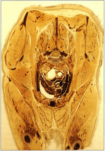 Figure 11. Cured P40 transverse body slice, near thoracic inlet of cat. |
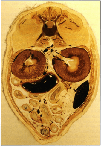 Figure 12. Cured P40 transverse body slice, mid-abdominal cavity of cat. |
The slices in the sealed flat chambers laid horizontal between the UVA lights do not migrate and will stay centered in the resin during curing. Non-sealed flat chambers which are cured upright or at an angle allow specimens to move/sink and special attention must be given at the appropriate time to keep the slices centered in the resin. Using P40 resin or P40 mixed with A4 have been equally successful at producing desirable specimens. The A4 addition is recommended to assure curing of the resin and prevent curing artifacts and prevent problems with curing from inadequate fixation (Henry, 1998). The advantage of not using A4 is the indefinite pot-life of the P40 impregnation bath if kept cool and in the dark. Without A4 additive, the same impregnation bath has been used for five years. As well, without the additive, impregnated slices may be stored for years before casting (when timing is more convenient or when slices are needed for demonstration).
The impregnated slice is surrounded by polyester resin or mixture (P40/A4) while it is curing. Hence, the plastinated slices are incorporated into a single cured sheet of the resin. They are not merely embedded in the resin. The specimens show good delineation of white and gray matter and are durable, as well as demonstrate good anatomical detail for comparison with images of modem imaging modalities (Latorre et al., 2001; 2002; 2004; 2006 ; Rodriguez et al, 2006; Soler et al., 2007).
Polyester has several advantages over the epoxy technique:
Disadvantages:
The main advantage of the P40 sheet plastination method is the decreased volume of resin used, two thirds less, because there is no separate immersion bath ; as well, the P40 immersion/impregnation bath may be reused if no activator is used. Also the process is not complicated and less equipment and time is needed. P40 slices are excellent teaching aids for teaching sectional anatomy (Latorre et al., 2001; Henry, 2005c).
Barnett RJ. 1997: Plastination of coronal and horizontal brain slices using the P40 technique. J Int Soc Plastination 12(1):33-36.
https://doi.org/10.56507/YJVS5787
de Boer-van RT, Comelissin CJ, ten Donkelaar HJ. 1993: Sheet plastination of the human head. J Int Soc Plastination 6( 1):20-24.
https://doi.org/10.56507/PLZK5739
Gao H, Liu J, Yu S, Sui H. 2006: A New Polyester Technique for Sheet Plastination . J Int Soc Plastination 21 :7-10.
https://doi.org/10.56507/JPVW6850
Henry RW. 1998: Update on polyester plastination (P40)! Where have all the "orange spots" gone? Abstract presented at The 9th International Conference on Plastination, Trois-Rivieres, Quebec, Canada, July 5-10, 1998. J Int Soc Plastination 13(2):30.
Henry RW. 2005a: Vacuum and vacuum monitoring during silicone plastination. Abstract presented at The 8th Interim Conference on Plastination- Lake Ohrid, Macedonia, July 5-11, 2005. J Int Soc Plastination 20:37.
Henry RW. 2005b: Silicone impregnation and curing. Abstract presented at The 8th Interim Conference on Plastination- Lake Ohrid, Macedonia, July 5-11, 2005. J Int Soc Plastination 20:36-37 .
Henry RW. 2005c: Teaching with plastinated specimens in veterinary medicine. Abstract presented at The 8th Interim Conference on Plastination- Lake Ohrid, Macedonia, July 5-11, 2005. J Int Soc Plastination 20:38- 39.
Henry RW, Nel PPC. 1993: Forced impregnation for the Standard S10 method. J Int Soc Plastination 7(1):27-31.
https://doi.org/10.56507/WUXP9436
Henry RW, Weiglein A. 1999: Sheet plastination of brain slices - P40 procedure. Abstract presented at The 6th Interim Conference on Plastination, Rochester, New York, USA, July 11-16, 1999. J Int Soc Plastination 14(2):32.
Latorre R, Vaquez JM, Gil F, Ramirez G, L6pez-Albors 0, Orenes M, Martinez-Gomariz F, Arencibia A. 2001: Teaching anatomy of the distal equine thoracic limb with plastinated slices. J Int Soc Plastination 16:23-30.
https://doi.org/10.56507/ACRF7155
Latorre R, Vaquez JM, Gil F, Ramirez G, L6pez-Albors 0, Ayala M, Arencibia A. 2002: Anatomy of the equine tarsus: A study by MRI and macroscopic plastinated sections (S 10 and P40). Abstracts presented at The 11th International Conference on Plastination, San Juan, Puerto Rico, July 14-19, 2002. J Int Soc Plastination 17:6.
Latorre R, Arencibia A, Gil F, Rivero M, Ramirez G, Vaquez-Auton JM, Henry RW. 2004: Sheet Plastination with Polyester: An Alternative for All Tissues. J Int Soc Plastination 19:33-39.
https://doi.org/10.56507/OFGF7088
Latorre R, Arencibia A, Gil F, Rivero M, Henry RW, Ramirez G, Vaquez JM. 2006: Correlation of magnetic resonance images with anatomic features of the equine tarsus. Am J Vet Res 67:756-61.
https://doi.org/10.2460/ajvr.67.5.756
Rodriguez MJ, Agut A, Gil F, Latorre R. 2006: Anatomy of the equine temporomandibular joint: study by gross dissection, vascular injection and section. Equine Vet J 38:143-147 .
https://doi.org/10.2746/042516406776563378
Soler M, Murciano J, Latorre R, Belda E, Rodriguez, MJ, Agut A. 2007: Ultrasonographic, computed tomographic and magnetic resonance imaging anatomy of the normal canine stifle joint. Vet J 174:351-361.
https://doi.org/10.1016/j.tvjl.2006.08.019
Smith BJ , Holladay SD. 2001: Risk factors associated with plastination: IL Infectious agent considerations. J Int Soc Plastination 16:14-18.
https://doi.org/10.56507/GFGP6952
Sora MC. 1998: Plastination of three dimensional brachial plexus with P40. J Int Soc Plastination 13(1):12-14.
https://doi.org/10.56507/REZM6562
Sora MC, Brugger P, Traxler H. 1999: P40 plastination of human brain slices: Comparison between different immersion and impregnation techniques . J Int Soc Plastination 14(1):22-24.
https://doi.org/10.56507/XLSJ5724
von Hagens G. 1979a: Impregnation of soft biological specimens with thermosetting resins and elastomers. Anat Rec 194(2):247-255.
https://doi.org/10.1002/ar.1091940206
von Hagens G. 1979b: Emulsifying resins for plastination. Der Praparator 25(2) :43-50.
von Hagens G. 1986: Heidelberg Plastination Folder: Collection of technical leaflets for plastination. Biodur Products, Rathausstrasse 18, Heidelberg, 69126. pp 2:1-6, 3:1-13, 4:1-20, 5: 1-17.
von Hagens G. 1990: Preliminary Leaflet for Plastination of Brain Slices with Biodur™ P 35. Unpublished computer printout: August.
von Hagens G, Tiedemann K, Kriz W. 1987: The current potential of plastination. Anat Embryol 175(4):411-421 .
https://doi.org/10.1007/BF00309677
von Hagens G. 1994: Plastination of brain slices according to the P40 procedure. A step-by-step description. 23 pages.
https://doi.org/10.56507/OWYV2878
Weiglein AH, Feigl G. 1998: Sheet plastination of brain slices according to the P35 and P40 procedures. Abstract presented at The 9th International Conference on Plastination, Trois-Rivieres, Quebec, Canada, July 5-10, 1998. J Int Soc Plastination 13(2):30.
Product distribution:
Biodur Products, Ors. Gunther von Hagens and Angelina Whalley , Rathausstrasse 11, 69126 Heidelberg, Germany. www.biodur.de, Ph: (49) 6221 3311-11, Fax: (49) 6221 3311-12 .