Triton College, Visiting Associate Professor, University of Illinois at Chicago.
This paper proposes a standardized method for the teaching of sectional anatomy to correlate with computer imaging modality scans. The standardized method of sectional anatomy instruction has been previously discussed and illustrated (Lane, 1988, 1989, 1990 a,b, 1991) and sometimes referred to as the Lane method (Stuart, 1990). The first part of the methodology is to identify, regardless of plane, the area of the body from which the section is derived. For example, in axial sections, the distance from Reid's baseline (Infraorbital meatal line) (in the head), and vertebral levels (neck and trunk), can indicate the origin of the section. In sagittal sections, the distance of the section from the median plane is a convenient system. In this case, a need exists to indicate whether the section is from the right side or left side of the body.
Sectional Anatomy; E15; Sheet Plastination
Alexander Lane Coordinator of Anatomy and Physiology, Triton College, Visiting Associate Professor, University of Illinois at Chicago.

![]()


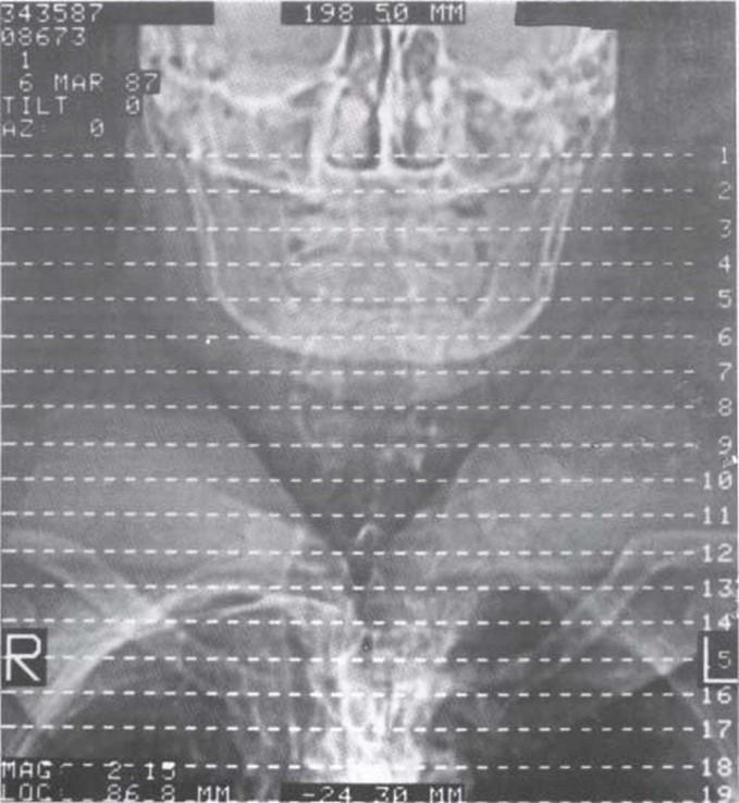
Figure 1. Computed tomography scan, showing the orientation lines for reference slices.
This paper proposes a standardized method for the teaching of sectional anatomy to correlate with computer imaging modality scans. The standardized method of sectional anatomy instruction has been previously discussed and illustrated (Lane, 1988, 1989, 1990 a,b, 1991) and sometimes referred to as the Lane method (Stuart, 1990). The first part of the methodology is to identify, regardless of plane, the area of the body from which the section is derived. For example, in axial sections, the distance from Reid's baseline (Infraorbital meatal line) (in the head), and vertebral levels (neck and trunk), can indicate the origin of the section. In sagittal sections, the distance of the section from the median plane is a convenient system. In this case, a need exists to indicate whether the section is from the right side or left side of the body. For frontal/coronal sections, the distance anterior or posterior to the midaxillary line is a suitable system for identifying the origin of a section. Orientation lines, also known as a grid, are needed in both cadaver and in vivo sections to further substantiate the derivation or origin of a section (Fig 1.)
It is important to keep in mind the surface orientation for each plane. For example, in a transverse/axial section, the inferior surface is observed to correlate with the standards of imaging modalities such as magnetic resonance imaging (MRI), computed tomography (CT) scan, and ultrasound. In frontal/coronal sections, the imaging modalities display the anterior surface of the sections. Thus, this custom is used in sectional anatomy. In the computerized imaging modalities, the sagittal section is viewed from the right side. Therefore, this custom is used in sectional anatomy. In some instances the sagittal plane sections are viewed from the left side.
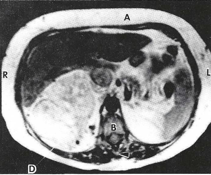 Figure 2. Magnetic resonance image. Transverse (axial) section of the abdomen which highlights the MUSCULOSKELETAL UNIT. A - Rectus abdominis muscle, Vertebra (8 - Body, arrowhead - spinous process), D - Hypernephroma. |
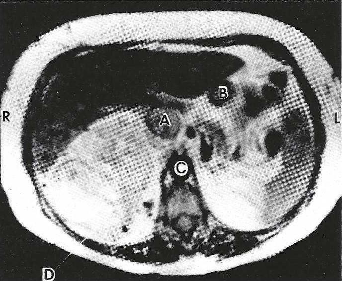 Figure 3. Magnetic resonance image. Transverse (axial) section of the abdomen which highlights the NEUROVASCULAR UNIT. A - Inferior vena cava, B - Hepatic portal vein, C - Descending abdominal aorta, D - Hypernephroma. |
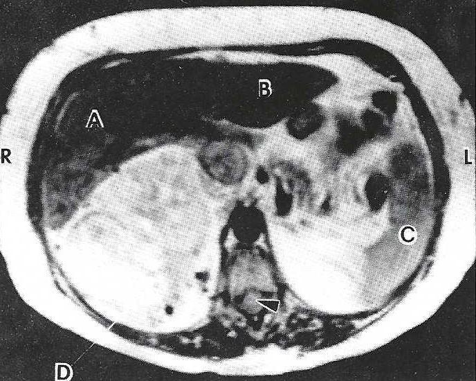 Figure 4. Magnetic resonance image. Transverse (axial) section of the abdomen which highlights the VISCERAL UNIT. Liver (A - Right lobe, B - Left lobe), C - Spleen, arrowhead - Spinal cord. |
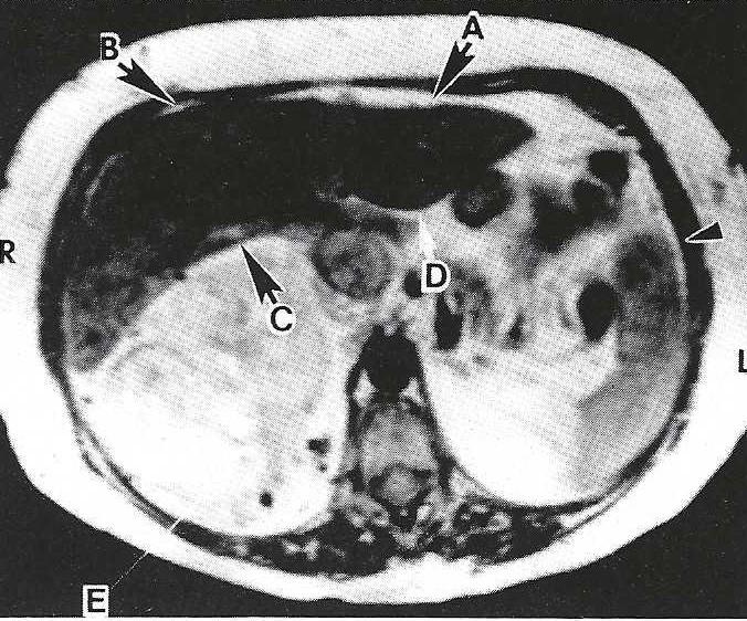 Figure 5.. Magnetic resonance image. Transverse (axial) section of the abdomen which highlights the ENCLOSIN UNIT. Subphrenic space (A - Left, B - Right), Subhepat1c space (C - Right, D - Left), arrowhead - Peritoneal cavity. |
Regardless of plane, the structures of each section would be classified into four anatomical units or categories. Figures 2, 3, 4, and 5 show examples of each anatomical unit using MRI axial (transverse) clinical slices of man. Note that a thrombus in the vena cava and a hyper nephroma of the right kidney are depicted. Figures 6, 7,8 and 9 show examples of each anatomical unit using sheet plastinated human sections. The four anatomical units and an explanation of structures included in each unit follows:
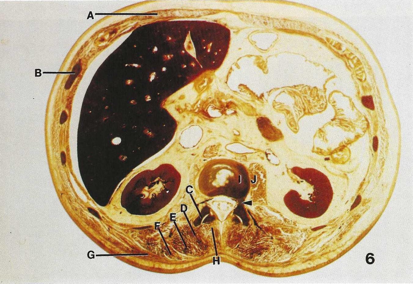 Figure 6. Sheet plastinated. Transverse (axial) section of abdomen which highlights MUSCULOSKELETAL UNIT structures. A - Rectus abdominis, B - Rib, C - Transverse process of a lumbar vertebra, D - Spinalis, E - Longissimus, F - Ilio-costalis, G - Latissimus dorsi, H - Multifidus, I - Body of lumbar vertebra, J - Psoas major, Arrowhead - Pedicle. |
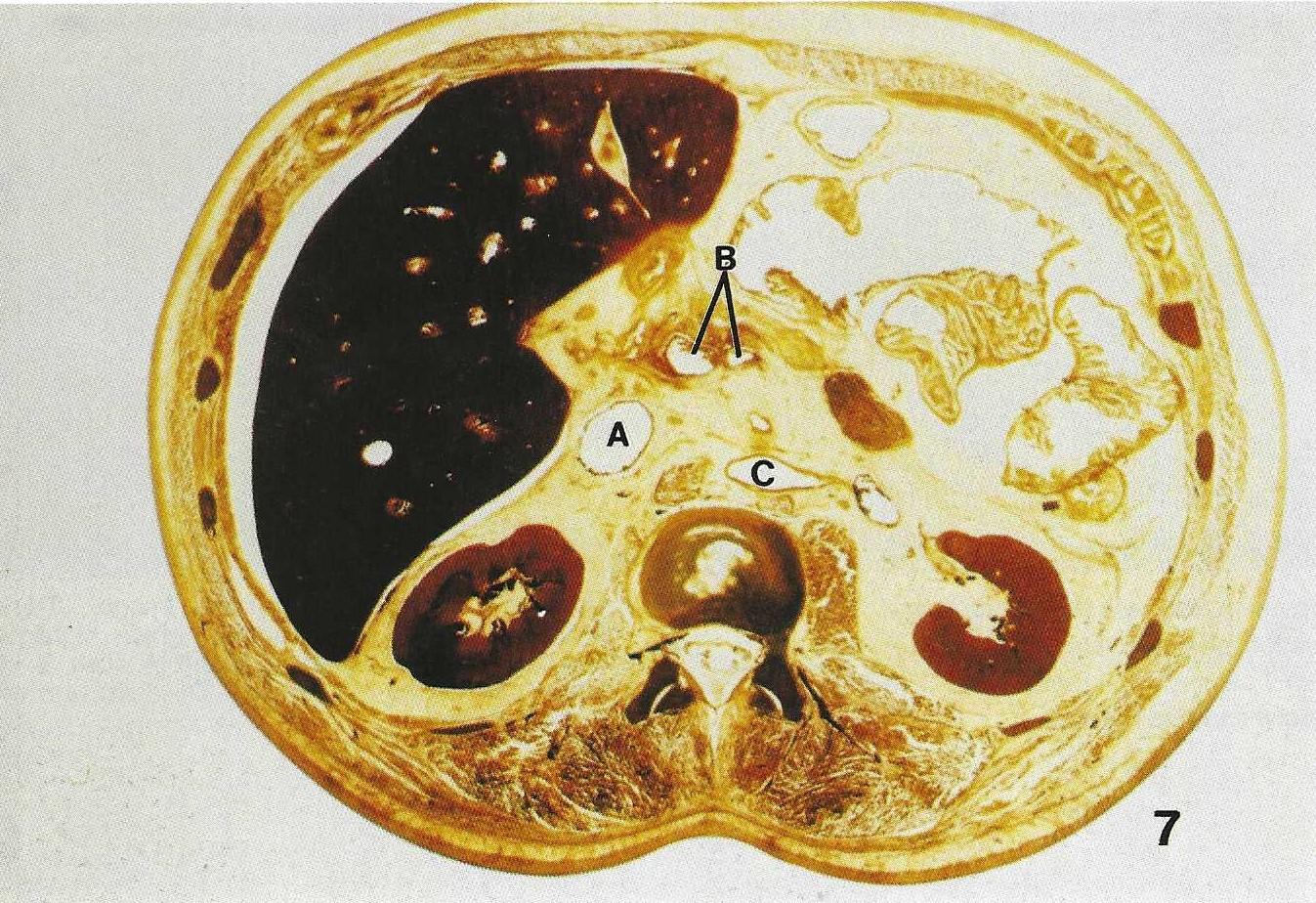 Figure 7. Sheet plastinated. Transverse (axial) section of abdomen which highlights NEUROVASCULAR UNIT structures. A - Inferior Vena Cava, B - Superior mesenteric vein and artery, C - Descending abdominal aorta. |
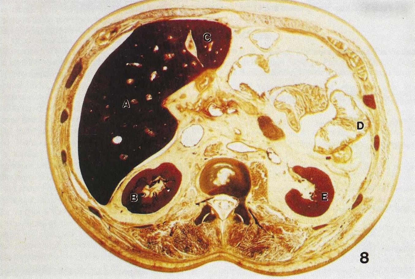 Figure 8. Sheet plastinated. Transverse (axial) section of abdomen which highlights the VISCERAL UNIT structures. A - Right lobe of liver, B - Right kidney, C - Left lobe of liver, D - Large bowel (colon), E - Left Kidney. |
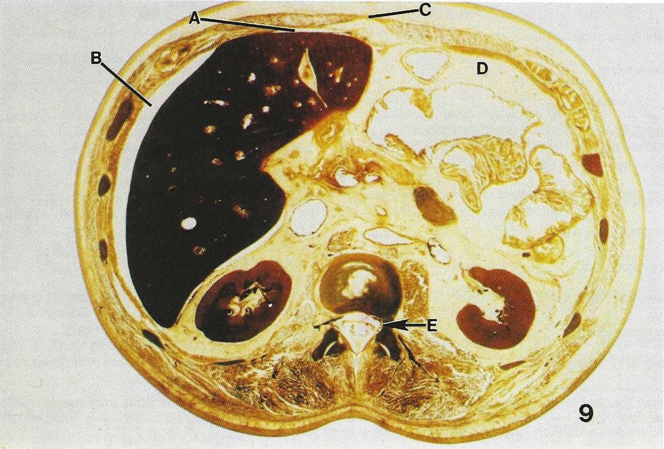 Figure 9. Sheet plastinated. Transverse (axial) section of abdomen which highlights the ENCLOSING UNIT structures. A - Left subphrenic space, B - Right subphrenic space, C - Linea alba, D - Peritoneal cavity area, E - Dura mater. |
Musculoskeletal unit - a group of bony features and muscular structures located in a section.
Neurovascular unit - a group of nerve structures and vessels as well as dural sinuses located in a section.
Visceral unit - a group of internal organs located in a section.
Enclosing unit - the membranes, spaces, fossae, and other special features seen within a section. Another aspect of this standard method of instruction for sectional anatomy includes the relationship of adjacent structures which may differ depending upon the plane in which a structure is seen. In transverse sections, anterior/posterior relations, as well as, lateral/medial relations are considered for each structure noted. For example, the internal jugular vein, in an axial section of the neck, is compared in location to a structure anterior to it, posterior to it, lateral to it, and medial to it.
In frontal/coronal sections, superior/inferior relation- ships, as well as, medial/lateral relationships are compared for each structure under consideration. In a coronal section at the midaxillary line, the arch of the aorta may serve as an example. In a section at this location, the trachea is usually seen superior to the arch of the aorta while the ascending aorta is inferior to it. The superior vena cava is seen lateral (right) to the arch, while the pulmonary trunk is seen lateral and left of the arch.
In sagittal sections superior/inferior relationships and anterior/posterior relationships are used in locating any structure. The trachea is used as an example here. The thyroid gland is seen anterior to the trachea and bodies of thoracic vertebrae are seen posterior to the trachea. The cricoid cartilage of the larynx is observed superior to the trachea in a mid-sagittal section, and the left primary bronchus may be seen at the inferior end of the trachea. The standard information about each structure varies. However, all structures should be described as seen in any particular section regardless of plane. In a mid- sagittal section the trachea appears as an elongated (superior to inferior), half cylinder shaped structure, whereas in a transverse section, it appears as a round structure. Another piece of information, which is standard regardless of plane, is the location of the structure.. The location of organs and structures can be determined by measurement using some assigned reference point. In some preliminary studies of transverse (axial) sections of the cadaver (Table 1), the junction of median and, midaxillary lines were used as the reference point. In addition, organs were located on the section using the clock face analogy. That is, on a cross section of the head, the frontal crest was assigned the 12:00 position and the internal occipital protuberance the 6:00 position.
|
|
Level | Distance | Angle 1 | Angle 2 | Clock |
| Internal occipital protuberance | 8 cm + | 65 | 90 | 0 | 6:00 |
| Internal occipital protuberance | 6 cm + | 72 | 90 | 0 | 6:00 |
| Superior sagittal sinus (anterior portion) | 8 cm + | 75 | 90 | 0 | 12:00 |
| Superior sagittal sinus (posterior portion) | 8 cm + | 70 | 90 | 0 | 6:00 |
| Internal jugular vein (R+) | 1 cm + | 40 | 42.5 | 46.5 | 7:30 |
| Internal jugular vein (Rt) | on line | 37.5 | 32.2 | 57.8 | 8:00 |
| Sternocleidomastoid (Rt.) | 1 cm + | 87.5 | 41.1 | 48.9 | 7:30 |
| Sternocleidomastoid (Rt.) | on line | 83 | 42.0 | 48.0 | 7:30 |
| Temporalis (Rt) | 1 cm + | 46 | 30.7 | 59.3 | 10:00 |
| Temporalis (Rt) | on line | 68 | 35.5 | 54.5 | 10:00 |
| Trapezius (Lt) | 1 cm + | 99 | 75.9 | 14.1 | 5:30 |
| Trapezius (Lt) | on line | 97.5 | 77 | 13 | 5:30 |
| Semispinalis capitis (Rt) | 1 cm + | 83 | 68.1 | 21.9 | 6:50 |
| Semispinalis capitis (Rt) | on line | 84 | 72.2 | 17.8 | 6:30 |
| Vomer bone | 1 cm + | 13 | 90 | 0 | 12:00 |
| Nasal septum | 1 cm + | 72 | 90 | 0 | 12:00 |
| Spinal cord | 1 cm + | 53 | 90 | 0 | 6:00 |
| Vitreous body of the left eye | 1 cm + | 74 | 58.3 | 31.7 | 1:00 |
| Nasopharynx | 1 cm + | 6 | 90 | 0 | 12:00 |
| Maxillary sinus (Rt) | 1 cm + | 43 | 59.4 | 30.6 | 1:00 |
| Sphenoid sinus | on line | 18 | 90 | 0 | 12:00 |
| Condyle of mandible (Lt) | on line | 54.5 | 0 | 90 | 9:00 |
| Temporal lobe (Lt) | on line | 46 | 40.7 | 49.3 | 1:30 |
| Medulla oblongata | on line | 35 | 90 | 0 | 6:00 |
| Level: "on line" = Reid's baseline, "+" = above Reid's baseline; Distance = Millimeters from median-midaxillary junction; Angle 1 = Angle with midaxillary and median-midaxillary junction (degrees); Angle 2 = Angle with median and median-midaxillary junction (degrees); Clock = clock face position. | |||||
In addition to location and description of a structure, other information gathered depends upon the kind of structure under consideration. In structures of the musculoskeletal unit, histological class of bone (cancellous or compact) and origin and insertion of muscles should be specified. In the neurovascular unit, origin, distribution, and course of arteries should be noted. Veins and lymphatic vessels should be described in a similar manner, but instead of distribution, termination is more appropriate. The origin, + distribution, and course of each nerve seen in the section should be noted. For structures included in the visceral unit, size (as seen in the section), course, and major functional role should be discussed. However, for the structures of the enclosing unit, description and location are adequate. For example, the interpleural space is seen in thoracic sections as an empty circular space between the visceral and parietal pleurae.
ACKNOWLEDGEMENTS:
Bruker Medical Imaging, Inc., Lisle, Illinois, provided the MRI scans. W. B. Saunders Co. published "Modern Sectional Anatomy" (Lane and Sharfaei) which is based on this methodology.
Lane A, H Sharfaei, Modern Anatomy: The Sectional Approach Trition College Press and Trition College Staff Service Center, 1988.
Lane A, Teaching Sectional Anatomy with Sheet Plastinated Sections, presented at The 1st Interim Meeting on Plastination, Knoxville, TN USA, November 3 & 4,1989 J Int Soc Plastination 3(1):38, 1989.
Lane A, Sectional Anatomy: Standardized Methodology, Paper from Fourth Annual Conference May 4, 1990, Chicago Illinois on Teaching and Technology: The Role of Computers in the Educational process at University of Illinois at Chicago and City Colleges of Chicago Partnership Program.
Lane A, Sectional Anatomy: Standardized Methodology In: Curriculum Resources for Teaching Sectional Anatomy Report #2 1990, The American Sectional Anatomy Consortium.
Lane A, H Sharfaei, Modern Sectional Anatomy, W.B. Saunders Co. 1st edition (In Press for 1991).
Stuart C, Sectional Anatomy: Modern look at "flat: world". In: At Chicago (newspaper) 8(20), March 7, 1990.