Department of Anatomy with Radiology, School of Medicine, University of Auckland, New Zealand.
The E12 epoxy method of sheet plastination for preparing thin, transparent and serially sectioned cadaveric teaching specimens has been utilized primarily for studying sectional anatomy and correlation of MRI and CT radiographic images. The unique properties of the E12 process offer an exceptionally vivid survey of the human body in any given plane resulting in precise delineation of the structural layout in situ. Maximum detail of sections is attained by large scale lipid extraction which enhances transparency.
Sections were prepared in sagittal, horizontal and coronal planes from different regions of the body including head and neck, trunk, inguinal region, limbs and joints. The macroscopic structures within these sections correspond precisely with images of the same structures obtained radiologically.
By introducing E12 sectional anatomy specimens to the anatomy teaching laboratory, the transition between gross anatomy and histology has been made possible by studying the one specimen. When utilized in our combined topographic anatomy and histology teaching laboratories, anatomical structures of thin and transparent slices can be magnified considerably. Standard histological slides providing detail of only a small area within predetermined parameters are often dictated by the physical limitations of the microscope slide itself. E12 sections provide a high degree of detail whilst retaining in situ structural integrity of the entire region in a complete and uninterrupted state.
One specimen provides students with significant gross detail down to the Submacroscopic level thus linking three disciplines, cross-sectional anatomy, radiology and histology. E12 plastinated sections have long been recognized as an ideal teaching aid in conjunction with radiological correlation, but it is in the microscopy laboratory that a valuable new dimension of this multi-disciplinary plastination technique has recently been realized.
Submacroscopy, Sectional Anatomy, Histology, Polymer E12
Peter Cook, Department of Anatomy with Radiology, Faculty of Medicine and Health Science, The University of Auckland, Private Bag 92019, Auckland, New Zealand. Telephone: 373 7599 / Fax: 373 7484. Email: pe.cook@auckland.ac.nz

![]()


The E12 epoxy method of plastination provides a number of opportunities to study the morphology of the human body in various forms and at various levels while using the one plastination technique (von Hagens, 1985). The development of the E12 method of sheet plastination was primarily an aid to conceptualize the human body in anatomical planes. Providing the undergraduate medical stu- dents with anatomical sections to aid their understanding of modern diagnostic imaging procedures such as computed tomography (C.T), magnetic resonance imaging (M.R.I), positron emission tomography (P.E.T), ultrasound and even gamma knife radiosurgery is an essential component of the curriculum in the Department of Anatomy with Radiology at the University of Auckland.
The unique characteristics of the E12 plastination technique has led to new and exciting directions in the teaching of anatomy to both undergraduate medical students and clinicians preparing for final fellowship examinations. Intro- duction of E12 sections to the student microscopy teaching laboratory, aided by closed circuit television, provides a transition between histology, radiology and clinically based gross anatomy all from one specimen (Cook, 1997). Sections are able to be viewed in their entirety and then may be magnified to various levels to display morphological relationships between contiguous structures ensuring an accurate representation of the morphology without the need for interconnected tissues to be physically separated. At high magnification E12 specimens correlate well with routine histological slides viewed by each student using conventional light microscopes. Joints, nerves, vessels, individual muscle fibres, the vasculature within nerves and even the vasculature within bone is easily identifiable, providing the student with views that have not been possible by conventional means.
Two cadavers of medium body weight with no wide- spread metastases, one male and one female, were used. Though not a prerequisite to the E12 technique, embalming was carried out using one of the techniques established in our laboratory (Cook and Dawson, 1996). In both cases arterial perfusion using the common carotid and femoral arteries in conjunction with venous drainage from the jugular and femoral veins were performed. A pre-injection vascular conditioner comprising of metaflow and rectifiant (Dodge catalogue, 1990) was perfused into the carotid arteries of the cadavers prior to embalming. Upon leaving the pre-injection mixture within the closed circulatory system for up to 30 minutes, vascular obstacles such as blood clots are rendered diffusible and non-coagulating allowing a more even distribution of embalming fluid. Following pre-injection, anatomical embalming was performed. The fixative solution of cadaver one consisted of mold x (500ml), phenol (1000ml), formalin (1500ml), chromatech (1000ml), monopropylene glycol (3000ml), methylated spirits (6000ml) and water (5000ml). The fixative solution of cadaver two consisted of metaflow (4000ml), rectifiant (4000ml), metasyn accelerated (5000ml), mold x (2500ml), icterine (25ml) and water (3500ml). Following embalming the cadavers were stored under refrigeration for several months. In readiness for serial sectioning each cadaver was cut into regions; head and thorax, abdomen, pelvis and extremities. To facilitate sectioning,
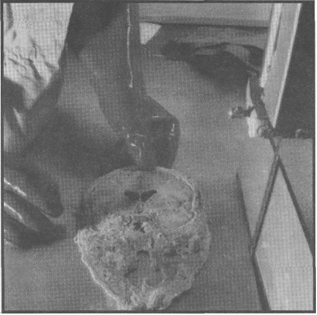
Figure 1. A whole head specimen was frozen to -80°C to facilitate sawing into thin 2.5 mm slices using an industrial meat cutting bandsaw.
these regions were frozen to -80°C for 4 days to ensure maximum firmness of the tissue. The frozen regions were serially sectioned using an AEW 350 high speed meat cutting bandsaw (AEW Engineering, Norfolk, England) equipped with a 4 tooth per inch Shark band blade (Alston et al., 1997). The bandsaw guide stop was cooled to -30°C for 4 hours prior to the commencement of cutting to retard early thawing of the frozen tissue. The guide stop was set for 2.5 mm cutting depth (figure 1).
The male cadaver was sectioned in transverse planes. Care was taken to ensure consistently even sections of an overall thickness of 2.5 mm to 2.8 mm. The pelvis, abdomen and half thorax of the female cadaver were sectioned sagittallly at 2.5 mm increments, while the head and remaining half thorax and shoulder were sectioned in coronal planes. Following sectioning, each slice was carefully cleaned, scraped free of tissue sawdust and laid flat on fiberglass screen mesh. The mesh supported sections were secured within special polypropylene grid baskets and immersed in the first of three acetone baths for dehydration by freeze substitution. Total dehydration time was 5 weeks. Purity of the final acetone bath remained at 99% for 3 days.
After complete dehydration of specimens, the final acetone bath was allowed to gradually warm up to ambient room temperature of 18°C to initiate degreasing. Yellowing of the acetone was an indication of lipid extraction from the sections thus requiring a change of solvent. The initial trial batch of four coronal head sections was degreased using only room temperature acetone as the choice of solvent. As transparency of the tissue is essential for obtaining the highest possible optical quality and differentiation of components within the finished sections, all subsequent specimens were then transferred from the yellow acetone to a pure bath of methylene chloride (dichloromethane) for a more thorough lipid extraction (Weber and Henry, 1993). Immersion in two baths of methylene chloride lasted for 8 weeks.
Due to the large number of sections to be processed, forced impregnation was carried out in batches of between 10 to 30 sections in the grid basket at any one time. Forced impregnation was carried out according to standard principles with the reaction mixture consisting of 95 p.b.w. (parts by weight) of E12 epoxy polymer, 5 p.b.w. of AE30 glass separator, 20 p.b.w. of AE10 plasticiser and 26 p.b.w. of E1 hardener (von Hagens, 1989). To retard early gelation of the reactive polymer mixture, temperature within the forced impregnation chamber was maintained at between zero and 5°C with a thermostat control built into the impregnation chamber. The impregnation chamber was sited within a standard household chest freezer.
Unlike other plastination methods where careful control of vacuum speed is essential, forced impregnation for E12 was rapid with a relatively vigorous bubbling of the volatile intermedium, which in this case was methylene chloride. After 48 hours of impregnation, absolute pressure was less than 1 mm Hg and bubbling had dropped off consider- ably. Vacuum was then discontinued (Cook and Barnett, 1996).
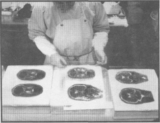
Figure 2. El2 impregnated coronal sections of the head are laid on sheets of glass in readiness for the casting and curing stage of the process.
In readiness for the casting and curing stage, toughened 5 mm thick glass plates were washed in a laboratory dishwasher at 95°C to remove previous deposits of hardened epoxy resin. A series of Styrofoam (polystyrene) blocks were positioned with glass plates, silicone gasket and foldback clips. The impregnated sections were removed from the grid baskets and excess El2 polymer was briefly al- lowed to drain back into the reaction mixture (figure 2). Some impregnation reaction mixture was deemed suitable for re-use in casting and was filtered to extract tissue fragments and lumps of clotted blood contaminants before being added to fresh casting resin as a cost saving measure.
Casting was carried out by 2 methods. Sections that were structurally sound enough to withstand the flat chamber assembly and filling stage, for example the head, pelvis and extremity sections were cast according to the flat chamber technique between two sheets of glass separated by a gasket of slightly greater thickness than the tissue slice to permit equal volume of resin to surround and stabilize the section on both surface areas (figure 3). For our purposes, the distance between the two sheets of glass was 8 mm, thus providing at least 2 mm coverage on either surface of the section. For the sections which could not structurally withstand the vertical orientation of the flat chamber casting process, such as abdominal slices where loops of bowel and projections of organs no longer attached to mesentery, fat or body wall were more than likely to collapse under their own weight, it was imperative to use the draining method (von Hagens, 1987). Each section was carefully sandwiched horizontally between two sheets of hostaphan foil.
Figure 3. Processed sections are positioned between sheets of glass forming a flat chamber. A special rubber gasket provides sufficient clearance between the section and each glass plate allowing resin to be poured around the slices.
Assembled flat chambers containing sections were filled with filtered, used impregnation resin mixed with fresh E12/ E1 resin. The ratio of used resin mixed with fresh resin was usually between 10% and 50%. Chambers were thoroughly checked for leaks and placed under vacuum for 45 minutes to extract air bubbles which became trapped under structures during the casting stage. Filled and deaerated flat chambers were then placed at an oblique angle and allowed to pre-cure for 24 to 48 hours. Following pre-cure (gelation), the flat chambers were placed in a laboratory heat cabinet at 45°C for 5 days.
Sections set up according to the draining method required removal of air bubbles by rolling and pressing bubbles to the edge of the foil or by extraction with a syringe and large bore spinal needle. These sections were kept flat and of even thickness with weighted sheets of glass and allowed to slowly gelate and cure at room temperature for 24 to 48 hours. Once cured, they were re-cast using flat chambers after removal of the foil.
Average tissue loss between sections from sawing was less than 1.0 mm. The total number of cut sections selected for subsequent processing amounted to some 175 sections. The finished E12 sections are semi-transparent, easy to orientate, correlate superbly with radiographs and above all else offer more detail right down to the submacroscopic level than is possible with any other plastination method or gross dissection in the anatomy examination laboratory. Successful results with the E12 technique are wholly dependent on specific parameters of section thickness and lipid extraction.
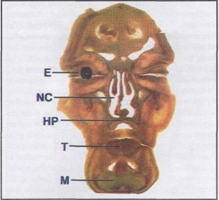
Figure 4. The first in a series of 25 serial coronal sections of the head. Visible are the eye (E), tongue (T), nasal cavity (NC), hard palate (HP) and mandible (M).
Comparisons between degreasing using only acetone, and degreasing using acetone followed by methylene chloride showed a marked difference in extent of detail and general appearance of the sections. In the case of methylene chloride adipose tissue assumed a high level of translucency with a notably clear appearance while degreasing with only acetone tended to give a pronounced yellowing to the tissue and inadequate clarity to the extent we require. Monitoring of E12 sections prepared using only acetone as both dehydration and degreasing mediums has tended to show a definite yellowing, or fading of both the tissue and the actual E12 resin itself over a prolonged time frame of several years.
Alternatively, E12 processing using acetone only as the de- hydration medium followed by methylene chloride as the degreasing medium has produced markedly better results which to date have not demonstrated any changes within the actual resin or the tissue section itself.
Examination of the head
Close examination of a coronal section through the frontal portion of the head (figure 4) offers a clear overview of the structures of the deep facial area. When magnified, (figure 5) the right eye from the specimen seen in figure 4 reveals a considerable amount of detail due to the plane of sectioning, thus preserving major components of the eye in an undisturbed state.
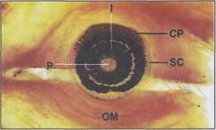 Figure 5. The right eye, magnified from figure 4 reveals considerable information due to the plane of sectioning, thus preserving the organ in situ. Visible are the pupil (P), iris (I), ciliary processes (CP), the sclerocorneal layer (SC) and orbicularis oculi (OM) muscle. |
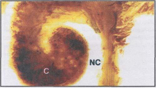 Figure 6. The nasal cavity (NC) when examined in coronal section reveals the extensive vascularity of the concha (C). |
Close examination of the nasal cavity reveals the ex- tensive vascularity of the conchae, which may not be read- ily observed in the dissecting room or histological specimen (figure 6). With an extraordinary degree of structural detail, E12 has distinct advantages over gross anatomy, radiology and histology in clarity of anatomical components.
The structure of the optic nerve, its meningeal covering and blood supply can be observed without any special preparation. The tongue, when seen in coronal section, provides a level of detail not readily seen using traditional dis- section methods. The pattern of muscle fibres within the substance of the tongue clearly shows the different groups with a vividly defined intermingling of extrinsic and intrinsic muscles as well as the branches of the hypoglossal nerve and lingual vessels. Within the same E12 section, detailed components of the roof of the oral cavity (mucosal lining, palatine glands, hard palate and floor of the nasal cavity) may be clearly seen. Although not expressly intended for plastination of the brain, the E12 method of sheet plastination provides a clear demarcation of the grey matter from the white matter. The column like arrangement of the actual fibre system of the cerebral cortex is not easily seen under routine light microscopy but may be observed well within E12 sections.
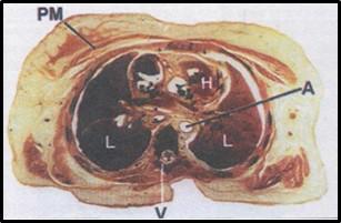
Figure 7. Transverse section through the thorax showing the layers of the body wall, lungs (L), heart (H), aorta (A), thoracic vertebra (V) and pectoralis major muscle (PM).
Examination of the thorax
A full E12 transverse section through the thorax (figure 7) allows orientation with various layers of the body wall, the vertebral canal, heart, lungs and great vessels. When examining the same area by way of a coronal section through the shoulder and thorax (figure 8) students are afforded an even clearer view of the grouping of intercostal muscles in addition to the shoulder joint and its relations. When magnified, students are able to truly appreciate the relative size of the wedge shaped external intercostal muscle in comparison with the significantly smaller mass of the internal and innermost intercostal muscles. This section (figure 9) also shows the superficial lymphatics of the lung with car- bon deposits visible just deep to the visceral pleura.
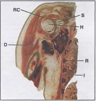 Figure 8. Coronal section of the shoulder region and thoracic wall showing the rotator cuff (RC) fusing with the capsule of the shoulder joint, ribs (R), intercostal muscles (I), lung (L), deltoid muscle (D), scapula (S) and head of the humerus (H). |
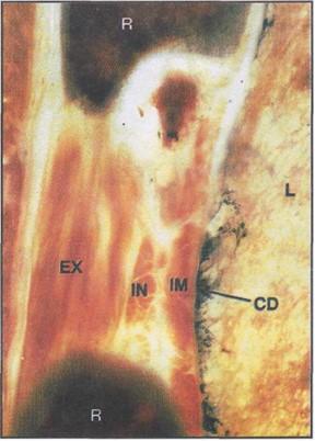 Figure 9. A close view of the thoracic wall magnified from figure 8 revealing rib (R), lung (L) and the arrangement of the external (EX), internal (IN) and innermost (IM) intercostal muscles. The superficial lymphatics of the lung are delineated with carbon deposits (CD) evident, just deep to the visceral pleura. |
Examination of the abdomen and pelvis
A multitude of anatomical information is obtained from the full sagittal section through the female pelvis and abdomen (figure 10). The vertebral canal and its contents, the stomach, transverse colon, duodenum, jejunum, various loops of ileum, rectum, vagina, uterus and bladder are all easily viewed. Close up study of the small and large intestine (figures 11,12,13) provides highly detailed information of the layers of the wall and pattern of its blood supply. The microvascular submucosal plexuses are clearly shown with- out additional Colour enhancement.
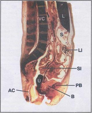 Figure 10. Median sagittal section through the female pelvis and abdomen demonstrating the gut, its relations and blood supply. The female internal genitalia and its relations with the urinary bladder and rectum are also clearly shown. VC - vertebral column, L - liver, S - stomach, LI - large intestine, SI - small intestine, B - urinary bladder, U - uterus, AC - anal canal, PB - pubic bone. |
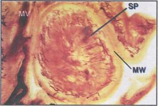 Figure 11. In this loop of ileum enlarged from figure 10, we can examine the external blood supply, in the form of a branch of mesenteric vessel (MV). The internal distribution of blood vessels in the form of a submucosal plexus (SP) is well defined as a distinct ring within the ileum itself. MW - muscular wall. |
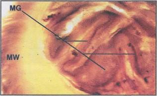 Figure 12. The fine line between gross anatomy and histology is illustrated in this example which clearly demonstrates the actual mucosal glands (MG) within the epithelial lining of the sigmoid colon. The muscular wall (MW) is also observed. |
In comparison with histology slides, the relative thickness of the tissue within the E12 sections allows structures to retain a readily seen three dimensional aspect. This allows the student an opportunity to not only identify individual components, but also to identify the pathways of structures in relation to surrounding tissues with great accuracy (figure 11). Looking at the urinary system as seen in a sagittallly sectioned pelvis and abdomen opens up excellent opportunities to correlate gross anatomical structures with their histological counterparts. Examination of the kidney for example gives the student an informative profile of the capsule, cortex, medulla, medullary pyramids and renal microvasculature down to the glomeruli. Examination of the ureter in E12 sections with magnification reveals the characteristic folding of the epithelium of the ureter which is identical to histology slides as seen in the microscopy laboratory with the added benefit of not having been removed from the abdomen. E12 preparation of the urinary bladder demonstrates not only the whole thickness of the bladder wall, but the interlacing pattern of smooth muscle bundles that run longitudily, transversely and obliquely. To fully appreciate the fine line between gross anatomy and histology, we are able to clearly identify and compare the actual mucosal glands within the epithelial lining of the sigmoid colon in an E12 sectioned pelvis with a similar histological slide of the same organ with remarkable clarity. Additionally, the smooth muscle wall of the colon is also well presented (figure 12). No better concept of the relationships of tissues within the anorectal region may be realized than in the series of transverse E12 sections taken through the male pelvis. The intense vascularity of the region becomes readily apparent with this plastination method such as the mucosal and submucosal plexuses of the anal canal. The differing muscle types are no better contrasted as the smooth muscle making up the internal anal sphincter and the skeletal muscle making up the external anal sphincter (figure 13). The appearance of the prostate in the sections produced in the E12 technique is an excellent example of submacroscopy. In standard transverse section the prostatic urethra, the urethral crest, prostatic sinuses and even prostatic concretions, in the form of small spherical granules of glycoprotein in the prostatic glandular tissue, are observed. Posterior to the bladder and the prostate an excellent internal profile of the seminal vesicles and the ampulla of the ductus deferens in situ are seen. Further study of the male reproductive organs are well presented by the spermatic cord in which we may identify the pampiniform venous plexus, testicular vessels and the ductus deferens. Transverse sections of the perineum at the level of the male external genitalia demonstrates most accurately the structure of the penis. The various fascial layers between the skin and the tunica albuginia, corpora cavernosa, penile urethra, corpus spongiosum and the dorsal vein of the penis are illustrated (figure 14).
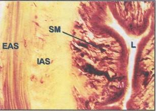 Figure 13. The complete structure of the anal canal may now be realized with the E12 process. In this close view, lumen (L), mucosa (M), submucosa (SM) rich in vasculature, internal anal sphincter (IAS) (smooth muscle fibres) and the external anal sphincter (EAS) (skeletal muscle fibres) are observed. |
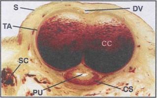 Figure 14. A complete profile of the external male genitalia is provided with the El2 plastination technique. The constituents of the penis including the various fascial layers between the skin (S) and the tunica albuginia (TA) are presented. Also visible are the corpora cavernosa (CC), penile urethra (PU), corpus spongiosum (CS), the dorsal vein (DV) of the penis as well as the spermatic cord (SC). |
Examination of the musculoskeletal system
Transverse sections through the pelvis, at the level of the hip joint offer a considerable degree of detail with numerous anatomical landmarks such as the gluteal muscles, the ischium, sciatic nerve and even examples of differing bone consistency, spongy and compact, within two examples of the femur. Bone diseases, for example osteosarcoma of the tibia, and its effects on surrounding tissues can be readily examined. Joints present superbly, with certain joints gaining a level of visibility not possible without the E12 method. By magnifying an area of transversely sectioned pelvis, students may gain an insight into the synovial cavity of the sacro-iliac joint whereby hematopoietic tissue (bone marrow), articular cartilage, joint cavity and internal features of the adjacent bone become clearly visible (figure 15). On subsequent transverse sections, observations of the hip joint at the level of the mid head of the femur are unique in as much as they clearly demonstrate not only the joint cavity, ligament of the head of the femur, acetabulum and articular cartilage, but also the blood supply to the head of the femur by way of the foveolar artery situated within the ligament of the head of the femur. In addition to normal anatomy, a lesion or cyst present in the bone can be readily seen (figure 16).
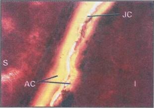 Figure 15. Sacroiliac joint showing articular cartilage (AC), synovial joint cavity (JC) and hematopoietic tissue (bone mar- row) of the sacrum (S) and the ilium (I). |
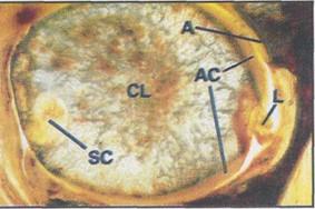 Figure 16. Transverse section of the hip joint demonstrates the acetabulum (A), articular cartilage (AC), ligament of the head (L), cancellous bone lamellae of the head (CL) and in this case a subchondral cyst (SC) laterally. |
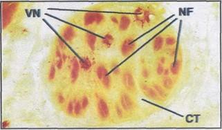
Figure 17. The sciatic nerve, as part of a transverse pelvic section, reveals the individual nerve fascicles (NF) separated by extensive connective tissue (CT) and the blood supply, vasa nervorum (VN) within the nerve itself.
Examination of the spinal cord and nerves
Nervous tissue is well represented in cross sections and compares precisely with histological slides, yet retaining the complete, uninterrupted attributes which are the foundation of the E12 method. A close view of the sciatic nerve as seen in the full transverse section shows the extensive amount of connective tissue separating the
individual nerve fascicles (figure 17). Additionally the vasa nervorum, the vasculature within the nerve, can also be identified as easily as in histological form. When magnified under the television system in the teaching laboratory, the complete pro- file of the spinal cord and vertebral canal is readily accessible. Fine details of the cross section of the cord, including the meningeal coverings, spinal nerve roots and rami are all visible in one section (figure 18).
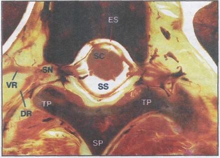 Figure 18. In this close view of figure 7 we can see the transverse processes (TP), spinous process (SP), epidural space (ES), subarachnoid space (SS), the spinal cord (SC), ventral ramus (VR) and dorsal ramus (DR) traceable to the spinal nerve (SN). |
Since its inception some eighteen years ago, plastination has grown and found its place among many mostly science based institutions around the world. The four major methods of plastination (S10, P.E.M, P35 and E12) collectively provide a cost effective means for preserving and presenting perishable biological specimens with each of these primary techniques having either generalized applications, or limited specific applications (von Hagens et al., 1987). The amount of anatomical information which can be attained is highly variable according to the characteristics of the individual class of polymer and method of processing. The S10 technique is an all purpose means for preserving whole or dissected tissues while retaining their natural shape, con- tours and to some extent colour (Henry and Nel, 1993).
P.E.M specimens typically, though not exclusively, are cross sectional specimens of considerable thickness and offer a better degree of detail of cut surfaces than is possible with the S10 method (Lischka and Prihoda, 1987). P35 is only suitable for preparing relatively thin brain slices using the sheet plastination method. Detail in P35 specimens is extremely precise and sectioned neuroanatomical structures are considerably better defined than is possible with either S10 or P.E.M though the use of this method is limited (Weiglein, 1996).
It has been reported that tissue sections prepared ac- cording to the E12 process may be made to more than 5 mm in thickness and processed with satisfactory results (Whalley, 1994). In our experience tissue sections of greater than 2.5 mm in thickness will exhibit a distinct loss in clarity with many structures superimposed and difficult to discern. With attention to obtaining and demonstrating very fine submacroscopic detail within our finished E12 specimens, it was critical that the uniformity of section thickness be maintained at no greater than 2.5 mm in thickness through- out the ongoing E12 program. Though most plastinators engaged in sheet plastination use a sliding cutting table on the bandsaw, we prefer to use a fixed table bandsaw for reasons of safety and hygiene whilst still achieving accurate sections during the sawing phase.
The removal of lipid content from already sawed body slices is an essential procedure of the success of the E12 technique. Acetone, as well as being the recommended medium for dehydration by freeze substitution, serves as an adequate degreasing solvent when subjected to room temperature or slightly higher. Although not mandatory, our experiences demonstrated that by far the highest optical quality of El2 sections were achieved from tissue sections that had been degreased in acetone at room temperature, then transferred to methylene chloride for more extensive lipid extraction.
The casting of abdominal slices by the draining method has proven to be vital to avoid dislodging of structures that would otherwise not survive the standard flat chamber process. Sections prepared according to this method had no supporting layer of polymer on either side. It was necessary to re-cast them using the flat chamber method to ensure a uniform thickness of the finished specimens. The hostaphan foil was simply peeled away from the sections revealing a fully cured specimen thus eliminating any risk of collapse or damage to the delicate structures. The sections could now be re-cast to the desired thickness in between glass plates according to the flat chamber technique.
The E12 process, although only suitable for thin cross sectional specimens prepared according to the sheet plastination method, has in effect filled a void in undergraduate teaching. Students are provided with a clear, unimpeded overview of the planes of the body seen with a whole section. Specific regions are then partially magnified to relay a concept of the relationships of the surrounding tissues not present in histological slides. Finally, specific structures are highly magnified enabling submacroscopic observation of components of these structures. They closely correspond to histological features as seen by the student using traditional microscopic slides. By combining traditional, as well as modern teaching techniques, the student is provided with an altogether clearer concept and relevance of microanatomy, clinically based gross anatomy and radiology.
With experience with virtually every plastination method at the University of Auckland, the E12 technique has proven itself to be by far the most beneficial to the student in terms of providing a firm link between macroscopic and microscopic anatomy. Student appreciation and under- standing of microscopic anatomy has been enhanced by the easily accessible and above all else, in situ presentation of relevant anatomical information which is able to be attained from an individual E12 section.
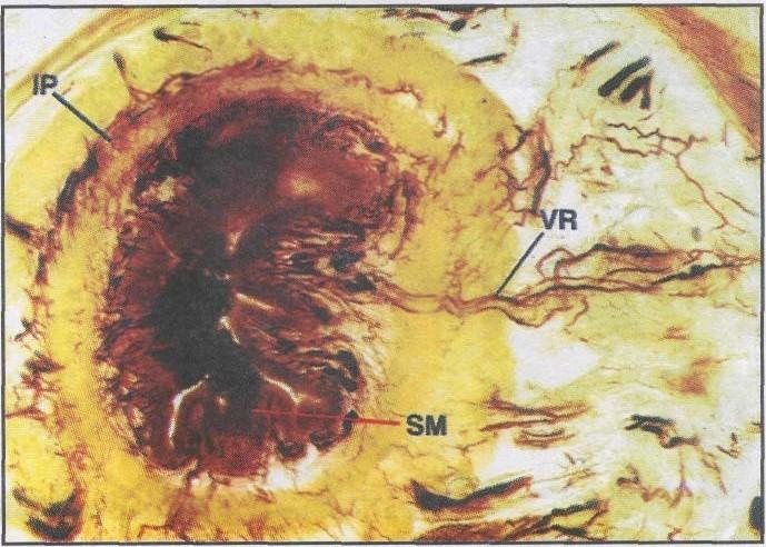
Figure 19. The arterial vasa rectae (VR) penetrating the wall of the large intestine. SM - submucosal vascular plexus, IP - intermuscular vascular plexus.
It is our aim to further develop the E12 process to include even thinner sections down to 1 mm or less, of specific organs and pathological anomalies. Investigation of injuries, diseases or primary lesions on target organs and the effects on other organs and structures such as bones, joints, vessels and nerves further removed from the site of the lesion, at both gross and submacroscopic levels is possible. Anatomic pathology can be extended to submacroscopic histopathology from a single section where we can study tumours of the paranasal sinuses and their effects on the surrounding region. Various diseases of the gut, for example the formation of the colonic diverticular dis- eases, could be substantiated through E12 submacroscopy. The arterial vasa rectae penetrate the wall of the gut resulting in muscular weakness, thus leading to a possible diverticular herniation of the colonic mucosa and sub mucosa (Cotran et al., 1994) (figure 19). Injuries to the vertebral column which could include vertebral disc prolapse and the effects on nerve roots and the spinal cord are good examples of the types of pathology that may be studied in these sections. By employing whole cross sections from all regions of the human body, students now are able to appreciate and better understand anatomical features, both generalized and specific (figure 20). With a ready supply of bequeathed cadavers and access to their relevant clinical in- formation, we are endeavouring to take 'submacroscopic' study to exciting new levels for both teaching and research opportunities.
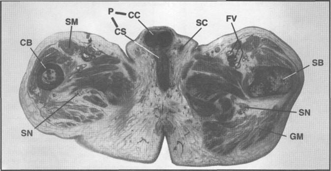 Figure 20. The male perineum and gluteal region seen in marginally oblique transverse section showing spongy (SB) and compact (CB) bony landmarks of the femur. Also visible are the corpus cavernosum (CC) and the corpus spongiosum (CS) of the penis (P), the spermatic cords (SC), gluteal muscles (GM), the sciatic nerves (SN), femoral vessels (FV) and sartorius muscle (SM). |
Acknowledgments
The authors would like to personally acknowledge the skillful assistance of Mr. Mark Shelley for his photographic expertise and general contributions to this paper.
Alston M, Janick L, Wade RS, Weber W, Henry RW: A shark band saw blade enhances the quality of cut in preparation of specimens for plastination. J Int Soc Plastination 12(1): 23-26, 1997.
https://doi.org/10.56507/OLQF4216
Cook P: Sheet plastination as a clinically based teaching aid at the University of Auckland. Acta Anat, 158(1): 33-36, 1997. https://doi.org/10.1159/000147907
Cook P, Barnett R: Practical Applications in Plastination. Instructional videotape, Departments of Anatomy, University of Auckland and University of Otago, New Zealand, 1996.
Cook P, Dawson B: An improved method of embalming suited to subsequent plastination requirements. J Int Soc Plastination, 10(1): 34, 1996. https://doi.org/10.56507/AHUU1684
Cotran R, Kumar V, Robbins S: Robbins pathologic basis of disease. 5th international edition, WB Saunders co., Montreal, pp 755-829, 1994.
Dodge Catalogue, Dodge Chemical Company, Cambridge, Massachussetts, pp 6-13, 1990 Edition.
Henry RW, Nel PPC: Forced impregnation for the standard S10 method. J Int Soc Plastination 7(1): 27-31, 1993.
https://doi.org/10.56507/WUXP9436
Lischka M, Prihoda M: Plastination of whole body slices with polymerising emulsion. J Int Soc Plastination 1(1): 17-22, 1987. https://doi.org/10.56507/TJJM6951
von Hagens G: Heidelberg Plastination Folder: Collection of all technical leaflets for plastination. Anatomische Institut 1, Universitat Heidelberg, Heidelberg, Germany, 1985.
von Hagens G: Polymers for plastination, price list. Biodur products, Heidelberg, Germany, May 1989.
von Hagens G, Tiedemann K, Kriz W: The current potential of plastination. Anat Embryol 175(4): 411-421, 1987.
https://doi.org/10.1007/BF00309677
Whalley A: Biodur TM products - Polymers, Auxiliaries, and Equipment for Plastination. Heidelberg, Germany, 1994.
Weber W, Henry RW: Sheet plastination of body slices - E12 technique, filling method. J Int Soc Plastination, 7(1): 16-22, 1993. https://doi.org/10.56507/EZGX2343
Weiglein A: Preparing and using P35 and S10 brain slices. J Int Soc Plastination 10(1): 22-25, 1996
https://doi.org/10.56507/IXGV4189