Departamento de Anatomia y Embriologia, Facultad de Veterinaria, Universidad de Murcia, Campus de Espinardo, 30071 Murcia, Spain
Tendons and ligaments of the equine distal limb have a distinct anatomy with important functional and clinical implications. This article reviews the descriptive and topographic anatomy of this region using fresh-fixed and plastinated sections. The polymers used to plastinate the specimens were PR-10 from Corcoran Laboratories™ and SIO from Biodur™ Company. The results demonstrate that plastination is an adequate preservation procedure for soft tissue structures of the equine thoracic limb. The specimens plastinated with SIO polymer were better for anatomical detail.
R. LATORRE: Telephone: 34-968-364 97; Fax: 34-968- 364 47; E-mail: latorre@um.es

![]()


The knowledge of the normal anatomy of the equine thoracic limb is essential for understanding foot deformities or injuries (Denoix, 1994; Dyson and Denoix, 1995). A thorough knowledge of the sectional anatomy of thoracic limb structures and their interrelationships is crucial for accurate interpretation of diagnostic images as seen with ultrasonographic examination (Nicoll et al., 1993; Denoix et al., 1996; Denoix et al., 1997). The increased use of imaging technologies such as magnetic resonance imaging (MRI), computed tomography (CT) and ultrasonography suggests a need for more cross- sectional anatomic studies. Unfortunately, body slices prepared by traditional methods are often unpleasant to handle and prone to deterioration. The technique of plastination (von Hagens, 1985) produces dry, odorless, non-toxic and durable specimens that retain their original surface and cellular detail (von Hagens et al., 1987). Traditional polymers suitable for plastination can be used at room temperature but must be stored in a freezer. Most plastination laboratories perform the impregnation process in the freezer to insure a longer pot-life of the polymer reaction mixture. The recent introduction of polymers that can be used and stored at room temperature eliminates the need of a freezer for impregnation and polymer storage. In addition, processing specimens at a warmer temperature may make them less rigid and may increase their flexibility (Glover et al., 1998).
The aim of this paper is to explore the use of plastinated transverse sections as a model for understanding the tendons, ligaments, arteries, veins and other soft tissue structures in the distal horse limb. A comparison between the use of polymer from Biodur (Heidelberg, Germany) and from Corcoran Laboratories (Bay City, MI) was also done.
Equine thoracic limbs were obtained from horses at a slaughterhouse. Their ages ranged from one to three years and they were of random sex. The specimens were cleaned and shaved. The arteries, veins and synovial structures of the thoracic limb were injected with red, blue and green latex, respectively. White latex was colored using pigment paste (2% ppv): AC50 (red), AC52 (blue) and AC54 (green) (Biodur™, Heidelberg). The injection was done by manual pressure with 10 or 20 ml syringes. Arterial injection was carried out via the brachial artery in full-length limb preparations or via the median artery when specimens were separated at the radial carpal joint. When the latex mixture started to ooze from the radial artery and the palmar branch of the median artery, they were ligated. Injection was continued until red latex also oozed from smaller arteries and the pressure on the syringe increased. After arterial injection, venous injection was performed via one of the two palmar digital veins, as distal as possible to avoid filling defects due to interference by valves. The proximal ends of the veins were left open until blue latex started to ooze from them. The fetlock joint {Articulationes metacarpophalangeae) was injected via its palmar pouch. Both the pastern joint {Articulationes interphalangeae proximalis manus) and coffin joint {Articulations interphalangeae distales manus) were injected via their dorsal pouches. The digital sheath of the deep digital flexor and the superficial digital flexor tendons was injected between the tendons.
After latex injection, specimens were frozen for several days at -25°C. The frozen limbs were sectioned transversely from the radius to the hoof with a high- speed band saw at the desired thicknesses (0.5 to 1.5 cm.). Twenty sections were made from each thoracic limb. The cut surfaces of each section were rinsed with water and numbered before fixation. Photographs were taken of both surfaces of each section before and after fixation.
The sections were fixed in a 10% formaldehyde solution for 15-30 days at room temperature. After removal from the fixative, they were washed under running tap water for one day.
Dehydration was performed by freeze substitution in cold acetone (96 to 100% purity). The sections were submerged in plastic vats containing ten times the specimen volume of acetone at -20°C. Acetone was changed weekly until the water content was less than 1%. Dehydration time for each specimen was four to six weeks.
After slicing, fixation and dehydration, the slices were plastinated according to either the standard cold S10 technique (Biodur™, Heidelberg) or a room temperature process, PR-10 technique (Corcoran Laboratories™, Bay City, MI). Group 1 reaction mixture: Polymer SR10 + Catalyst SH03 (1% ppv) (Biodur™, standard S10 procedure, at -20°C) (von Hagens, 1985). Group 2 reaction mixture: Polymer Cor-Tech PR-10 + Cross linker CR-22 (5% pbw) (Corcoran Laboratories™, room temperature).
Vacuum was applied to the immersed sections and gradually increased for both groups until a pressure of 1-5 mm Hg was attained and bubbling had ceased.
The sections were removed from the polymer reaction mixtures. Polymer was allowed to drip from the slices. The slices were wiped clean of excess polymer. The impregnated specimens were placed in appropriate airtight containers and each group was exposed to their respective curing medium at room temperature.
Group 1: Cross linker SH06 (Biodur™, standard SI 0 procedure) (von Hagens, 1985). The specimens were placed into a curing chamber with S6, which was vaporized ten minutes daily for one week. During this period, it was necessary to wipe the specimens three to four times a day. Finally, the specimens were placed in a plastic bag for 2 months to contain the S6 vapors around the specimens and allow curing of the center of the specimen.
Group 2: Catalyst CT-30 Corcoran Laboratories™). The specimens were either placed in a curing chamber and catalyst was evaporated for one week or catalyst was sprayed onto the specimens and then the excess catalyst was wiped off. When the spray method was used, the specimens were placed in a plastic bag for 24 hours with most of the air removed. It was necessary to repeat this spraying and bagging process until the specimens were completely dry (two to three days). Clean material (cloth or paper) was always used to wipe the catalyst onto the specimens.
Each specimen was mounted onto a piece of methacrylate using fast gum (cyanocrylato). Some of the mounted slices were stored and displayed in a manufactured transparent methacrylate box (Fig. 1).
S10 impregnation (group 1) took at least two weeks and one week was needed for curing. Sections of group 2 (PR-10, Corcoran technique) were impregnated in three to four days. Curing was faster in group 2 when the catalyst was sprayed directly onto the specimen (two to three days). However, curing by evaporation took a minimum of five days.
Specimens plastinated via the S10 technique displayed better anatomical detail, while PR-10 specimens displayed an excess of cured polymer build up on their surface during and after curing. To remove this deposit, it was necessary to brush the slices several times. However, surface quality of specimens was improved if the catalyst (CT-30) was evaporated and the liquid not applied directly onto the specimens. With this modified curing technique, it was necessary to cure at least five days to stop oozing of polymer, but the results were better than when the catalyst was applied directly to the slice.
The final color of plastinated specimens in both groups was similar to that of fixed specimens. The latex color in the vessels and synovial structures darkened significantly two or three months after plastination in both groups.
The final plastinated sections of both group 1 and group 2 showed the exceptional potential of plastination to preserve anatomical structures. No apparent differences in preservation quality were observed between the SR10 (group 1) and the PR-10 (group 2) specimens, but the anatomical detail was sharper in S10 specimens.
Excellent correlation of anatomical structures can be seen in all sections, both before fixation and after plastination (Figs. 2 - 6). The relationships between muscles, tendons and vessels at the carpal joint are easily seen (Figs. 2, 3). The oval tendon shape of the extensor carpi radialis m. is observed near the axis of the limb as it crosses the dorsum of the carpus. The common digital extensor t. is seen on the craniolateral aspect of the radius and carpus while the lateral digital extensor m. is noted on the lateral aspect. The small extensor carpi obliqus m. (M. abductor digiti I longus) (Fig. 2) crosses the dorsal aspect of the carpus from lateral to medial. Its insertion is near the lateral collateral ligament of the carpus.
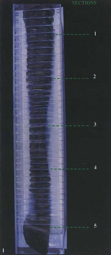 Fig. 1: Transverse sections of right thoracic limb at different levels (specimens mounted on transparent methacrylate she- ets and held in a transparent box). |
 Fig. 2: Fresh (A) and S-10 plastinated (B) section at the level of the distal radius (proximal view). |
In the metacarpal and digital regions (Figs. 4 - 6), the superficial digital flexor tendon, the deep digital flexor tendon, the accessory ligament of the deep digital flexor tendon and the suspensory ligament (M. interosseus) are readily observed. The tendon of superficial digital flexor crosses the palmar aspect of the carpus and the fetlock joint. It is nearly round in the carpal region (Fig. 3), becomes flattened in the metacarpal region (Fig. 4), and forms a ring around the deep digital flexor tendon as it crosses the fetlock joint. The tendon of the deep digital flexor lies deep to the superficial digital flexor tendon and is round in the metacarpal region becoming oval at the fetlock joint. The accessory ligament of the deep digital flexor (inferior/distal check ligament) is rectangular at its origin and lies deep to the deep digital flexor tendon (Fig. 4). The suspensory ligament is prominent in the metacarpal region between the second and fourth metacarpal bones (Fig. 4) having a rectangular shape. In the proximal metacarpal region it is located between the accessory ligament of the deep digital flexor muscle and the third metacarpal bone. The tendon sheath of the digital flexors encircles the superficial and deep digital flexor tendons (Fig. 4). The navicular bursa {bursae podotrochleares manus) (Fig. 6) is visible between the deep digital flexor tendon and the distal sesamoid bone.
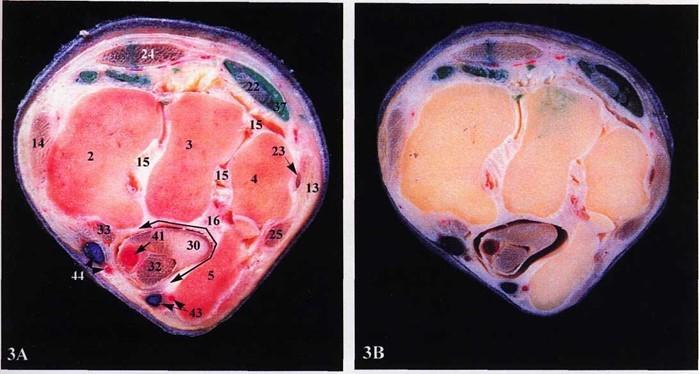 Fig. 3: Fresh specimen (A) and S10 plastinated specimen (B) at the level of the right proximal row of carpal bones (proximal view). |
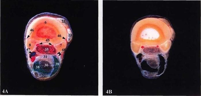 Fig. 4: Fresh section (A) and S10 plastinated section (B) of the right mid-metacarpal region (metacarpal bones, proximal view). |
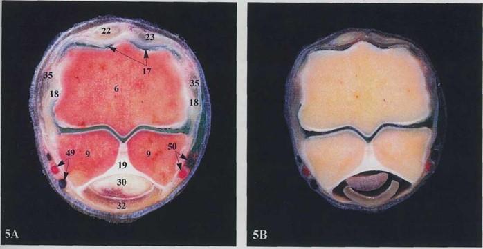 Fig. 5: Fresh (A) and SIO plastinated (B) sections at the level of the right fetlock joint (proximal view). |
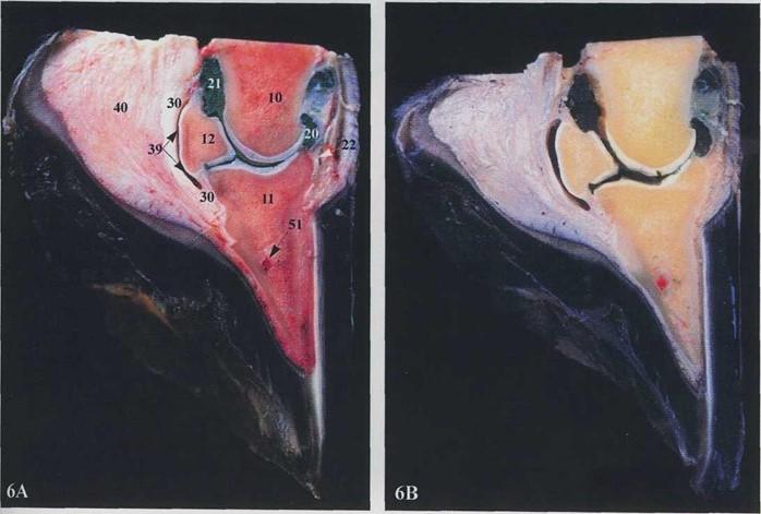 Fig. 6: Fresh (A) and SIO plastinated (B) sagittal sections at the level of the right coffin joint (axial view). |
Legends figures 2, 3 and 4: 1. Distal radius, 2. Radial carpal bone, 3. Intermediate carpal bone, 4. Ulnar carpal bone, 5Accessory carpal bone, 6. Cannon bone (Os metacarpal III), 7. Lateral splint bone (Os metacarpal IV), 8. Medial splint bone (Os metacarpal II), 13. Lateral collateral ligament of the carpus, 14. Medial collateral ligament of the carpus, 15 Intercarpal ligaments, 16. Carpal canal, 22. Common digital extensor m., 23. Lateral digital extensor m., 24. Extensor carpi radialis t., 25. Extensor carpi ulnaris m. {ulnaris lateralis), 26. Extensor carpi obliqus m., 27. Deep digital flexor m., humeral head, 28. Deep digital flexor m., ulnar head, 29. Deep digital flexor m., radial head, 30. Deep digital flexor t, 31. Accessory ligament of deep digital flexor m., 32. Superficial digital flexor m., 33. Flexor carpi radialis t., 35. Suspensory ligament, 34. Flexor carpi ulnaris m., 36. Antebrachial fascia, 37. Tendon sheath of common digital extensor t., 38. Tendon sheath of digital flexors, 41. Median a. & v., 42. Collateral ulnar a. & v., 43. Palmar branch a. & v., 44. Radial a. & v., 45. Palmar metacarpal arteries II & III, 46. Dorsal metacarpal arteries, 47. Medial palmar a. & v. {A & V. digitalis palmaris communis II), 48. Lateral palmar a. & v. {A & V. digitalis palmaris communis III), 52. Cephalic vein.
Legends figures 5 and 6: 6. Cannon bone (Os metacarpal III), 9. Proximal sesamoid bone, 10. Middle phalanx, 11. Distal phalanx, 12. Navicular bone (os sesamoideum distale), 17. Dorsal pouch of fetlock joint, 18. Collateral ligament, 19. Palmar ligament, 20. Dorsal pouch and 21. Palmar pouch of coffin joint, 22. Common digital extensor t., 23. Lateral digital extensor t., 18. Deep digital flexor t., 32. Superficial digital flexor t., 18. Suspensory ligament, 39. Navicular bursa, 40. Digital cushion [Tela subcutanea tori (pulvinus digitalis)], 49. Medial digital a. & v. (palmaris propia IT), 50. Lateral digital a. & v. (palmaris propia III), 51. Terminal arch.
Blood vessels can be readily identified on the plastinated section. For example, the median artery is seen on the caudomedial surface of the forearm (antebrachium), passing through the carpal canal with the flexor tendons. The palmar ramus and the radial artery (Fig. 3), which contribute to the palmar and dorsal metacarpal arteries are visible. The paired digital arteries (Fig. 5) pass over the abaxial surfaces of the proximal sesamoid bones.
With the S10 technique (group 1), a longer processing time is needed than with PR-10. There is little published information available concerning the use of Corcoran laboratories polymer (PR-10). Impregnation and curing are both faster with the Cor- Tech method. This is in agreement with Glover et al. (1998). However, the final quality of sections plastinated with this room temperature process (Corcoran) must be researched and improved to produce specimens of comparable quality to the S-10 technique. Polymer build up on the surface of slices is a problem with this room temperature process. The evaporation of the catalyst (CT-30), rather than spraying it onto the specimens, during the curing of sections improves the quality of the specimens. This additional time renders this curing time similar to that of the Biodur technique.
Also, to produce good specimens in successive batches, it is necessary to add 2% (p.b.w) of cross linker to the Corcoran polymer reaction mixture prior to impregnation of a new group of specimens. Baker (1998) reported shrinkage percent with Cor-Tech PR-10 polymer to be 3% or less in most tissues. We did not measure specimen shrinkage for either technique. This would be interesting to do in future work.
The methacrylate storage box offered a convenient solution for storage of the slices in an orderly manner. As well, mounting the specimens on clear methacrylate allowed both sides of each numbered section to be studied.
The quality of our injections suggests that the use of anticoagulant and lavage prior to injection of the vascular system, as described by Martin-Orti et al. (1999), is not necessary in large animal specimens excised post mortem at the slaughterhouse. The vascular and microvascular anatomy of superficial and deep digital flexor tendons could also have been studied by using colored latex with barium sulphate as reported by Kraus-Hansen et al. (1992) Kraus et al. (1995). However, when observing our plastinated transverse sections in sequence, the vascularity of the tendons was also readily observed. The latex inside the smallest vessels or synovial structures became darker after two or three months. Pigment was mixed into the latex just prior to injection. Possibly the pigment was not stable in at least one phase of the plastination process. Grondin and Olry (1996) used a mixture of Biodur S10/S3/S6/S2 and colored it with AC50 for plastination and obtained good color as well as long-term stability of color.
The most common injuries in the metacarpal and digital regions affect four anatomical structures which are all visualized in the plastinated specimens (Figs. 4 - 6): the superficial digital flexor tendon, the deep digital flexor tendon, the accessory ligament of the deep digital flexor tendon (distal check ligament) and the suspensory ligament. Under clinical conditions, a knowledge of normal anatomy of these complex areas is critical for accurate diagnosis of tendon or ligament injuries (Denoix et al., 1996). Tendons or ligaments normally change in size and shape from their origin to insertion. Because of this variation, equine veterinarians appreciate plastinated specimens which demonstrate important anatomical structures. Also, plastinated anatomical sections have high clinical value when used together with other diagnostic imaging techniques such as radiology, MRI and CT (Baptista, 1989; Fritsch, 1996). For example, ultrasonographic observation of the flexor tendons and ligaments in transverse and sagittal planes of the metacarpal region of horses provides quantitative data relating to the macroscopic sections (Nicoll et al., 1993).
On the other hand, undergraduate anatomy students should find it easier to comprehend sectional anatomy using these specimens. They should have a clear and accurate overview of the expanse, limits and relationships of complex anatomical areas (Marigos et al., 1997; Latorre et al., 1998). Our students are using these sections in practical lectures with high didactic success. This type of material also offers numerous possibilities for education and for surgical practice and training.
Acknowledgements: This work was supported by the project: 0075/CV/99 (Ayudas para la realization de proyectos de investigation de la Consejeria de Cultura y Education. Comunidad Autonoma de la Region de Murcia).
Baptista C, Skie M, Yeasting RA, Ebraheim N, Jackson WT. 1989: Plastination of the wrist: Potential uses in education and clinical medicine. J Int Soc Plastination 3:18-21.
https://doi.org/10.56507/XENF9035
Baker JA. 1999: COR-TECH PR-10 Silicone: Initial Trials in Plastination Human Tissue. J Int Soc Plastination 14(2): 13-19.
https://doi.org/10.56507/XVUK7879
Denoix JM. 1994: Functional anatomy of tendons and ligaments in the distal limbs. Vet Clin North Am Equine Pract 10(2):273-322.
https://doi.org/10.1016/S0749-0739(17)30358-9
Denoix JM, Jacot S, Bousseau B, Perrot P. 1996: Ultrasonographic anatomy of the dorsal and abaxial aspects of the equine fetlock. Equine Vet J 28(1):54- 62.
https://doi.org/10.1111/j.2042-3306.1996.tb01590.x
Denoix JM, Busoni V, Olalla MJ. 1997: Ultrasonographic examination of the proximal scutum in the horse. Equine Vet J 29(2): 136-141.
https://doi.org/10.1111/j.2042-3306.1997.tb01655.x
Dyson SJ, Denoix JM. 1995: Tendon, tendon sheath, and ligament injuries in the pastern. Vet Clin North Am Equine Pract 11(2):217-233.
https://doi.org/10.1016/S0749-0739(17)30320-6
Fritsch H. 1996: Sectional anatomy of connective tissue structures in the hind foot of the newborn child and the adult. Anat Rec 246(1):147-154.
https://doi.org/10.1002/(SICI)1097-0185(199609)246:1<147::AID-AR16>3.0.CO;2-P
Grondin G, Olry R. 1996: Vascular patters of plastinated human hands with special reference to abnormalities of the arterial palmar arches. J Int Soc Plastination 10(1): 19-21.
https://doi.org/10.56507/SDTU3072
Glover RA, Henry RW, Wade RS. 1998: Polymer preservation technology: poly-cur. A next generation process for biological specimen preservation. Presented at The 9th International Conference on Plastination, Trois-Rivieres, Quebec, Canada, July 5-10, 1998. J Int Soc Plastination 13(2):39.
Kraus-Hansen AE, Fackelman GE, Becker C, Williams RM, Pipers FS. 1992: Preliminary studies on the vascular anatomy of the equine superficial digital flexor tendon. Equine Vet J 24( 1) :46-51.
https://doi.org/10.1111/j.2042-3306.1992.tb02778.x
Kraus BL, Kiker-Head CA, Kraus KH, Jakowski RM, Steckel RR. 1995: Vascular supply of the tendon of the equine deep digital flexor muscle within the digital sheath. Vet Surg 24(2): 102-111.
https://doi.org/10.1111/j.1532-950X.1995.tb01303.x
Latorre R, Vazquez JM, Gil F, Ramirez G, Lopez- Albors O, Arencibia A, Moreno F. 1998: Macroscopic interpretation of horse head sectional anatomy using plastinated S-10 sections. Presented at The 9th International Conference on Plastination, Trois-Rivieres, Quebec, Canada, July 5-10, 1998. J Int Soc Plastination 13(2):39.
Marigos M, Kekic M, Doran GA. 1997: Learning relational anatomy by correlating thin plastinated sections and magnetic resonance images: preparation of specimens. Acta Anat 158:37-43.
https://doi.org/10.1159/000147908
Martin-Orti R, Stefanov M, Gaspar I, Martin R, Martin-Alguacil N. 1999: Effect of anticoagulation and lavage prior to casting of postmortem material with Mercox R and Batson R 17. J Microscopy 195(Pt 2):150-160.
https://doi.org/10.1046/j.1365-2818.1999.00554.x
Nicoll RG, Wood AKW, Martin ICA. 1993: Ultrasonographic observations of the flexor tendons and ligaments of the metacarpal region of horses. Am J Vet Res 54(4):502-506. Nomina Anatomica Veterinaria, 4th ed. 1994: Zurich and Ithaca, NY: World Association of Veterinary Anatomists,.
von Hagens G. 1985: Heidelberg Plastination Folder: Collection of all technical leaflets for plastination. Heidelberg, Germany: Anatomische Institut 1, Universitat Heidelberg,.
von Hagens G, Tiedeman K, Kriz W. 1987: The current potential of plastination. Anat Embryol 175:411-421.
https://doi.org/10.1007/BF00309677